Agilent 4155C/4156C User’s Guide Vol.1, Edition 11 2-33
Installation
Mounting Connectors
To Make an Interlock Circuit
The interlock circuit is designed to prevent electrical shock when a user touches the
measurement terminals.
CAUTION You must install an interlock circuit on a shielding box to prevent hazardous
voltages when the door of the shielding box is open.
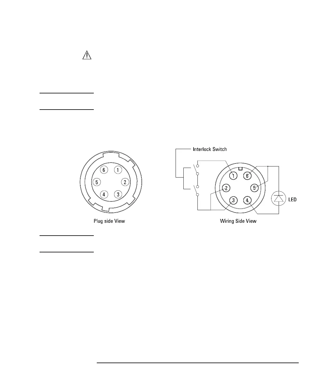
Figure 2-2 shows the pin assignments of the interlock connector mounted on a
connector plate or test fixture.
Figure 2-2 Interlock Connector Pin Assignments
WARNING Potentially hazardous voltages may be present at the Force, Guard, and Sense
terminals when the interlock terminals are shorted.
 Loading...