Service Guide 4-15
8719ET/20ET/22ET Start Troubleshooting Here
8719ES/20ES/22ES Digital Control Check
RF Network Analyzers
Digital Control Check
Observe the Power Up Sequence
Switch the analyzer power off, then on. The following should take place within a few
seconds:
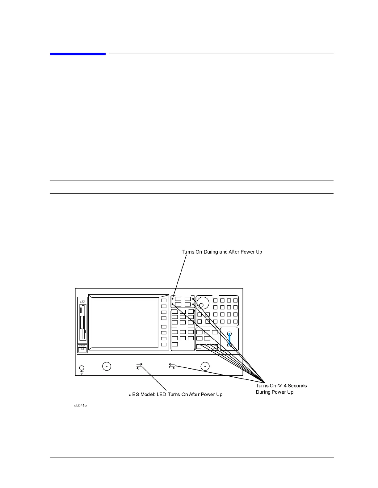
• On the front panel observe the following:
1. All ten ES model and eight ET model amber LEDs illuminate.
2. On the ES models, the TRANS REV and REFL REV LEDS near PORT 2 illuminate.
3. The amber LEDs go off after a few seconds, except the Chan 1 LED. At the same
moment, the TRANS REV and REFL REV LEDS near PORT 2 goes off.
NOTE On ET models, there is no TRANSMISSION LED on the front panel.
• The display should come up bright and focused.
• Five red LEDs on the A9 CPU board should illuminate and then turn off. They can be
observed through a small opening in the rear panel.
Figure 4-4 Front-Panel Power Up Sequence for ET and ES Models
 Loading...


