4-22 Service Guide
Start Troubleshooting Here 8719ET/20ET/22ET
Receiver Check 8719ES/20ES/22ES
RF Network Analyzers
Checking the R Channel Output (ET and ES Models)
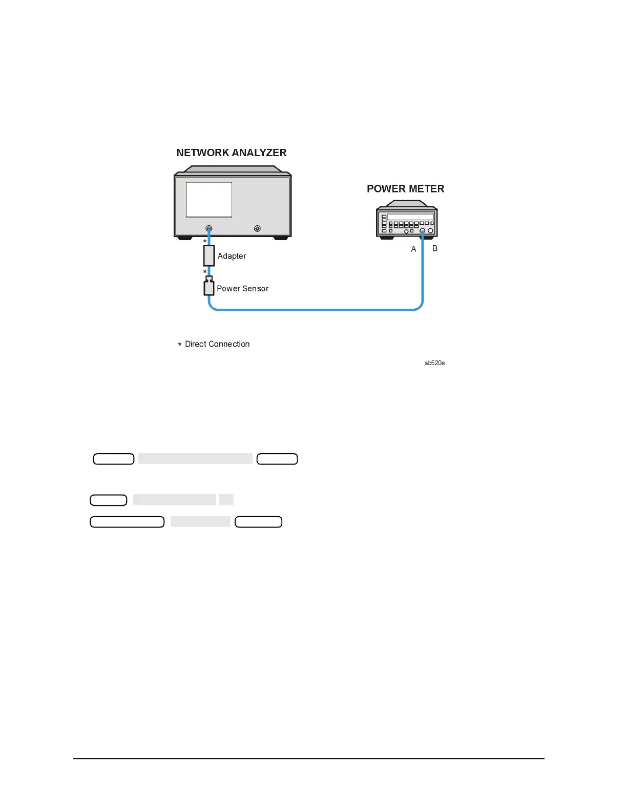
1. Connect the equipment as shown in Figure 4-5.
Figure 4-7 Setup for the R Channel Receiver Check (ES and ET Models)
2. Zero and calibrate the power meter. Set the calibration factor to the 1 GHz value. (See
the power meter manual for instructions on setting the calibration factor.)
3. Press the following:
4. Press the following:
5. Calculate the difference between the power meter reading and the marker reading on
the analyzer display. This power difference is the frequency response of the R channel.
6. Repeat steps 4 and 5 at the frequency points where a problem is suspected or check
different frequency points across the band (set the calibration factor on the power meter
for each frequency measured). For the characteristic values of the frequency response,
see Table 4-3 on page 4-21.
Preset
Preset
Meas
 Loading...


