2-20 Service Guide
System Verification and Performance Tests 8719ET/20ET/22ET
System Verification 8719ES/20ES/22ES
RF Network Analyzers
Equipment Initialization
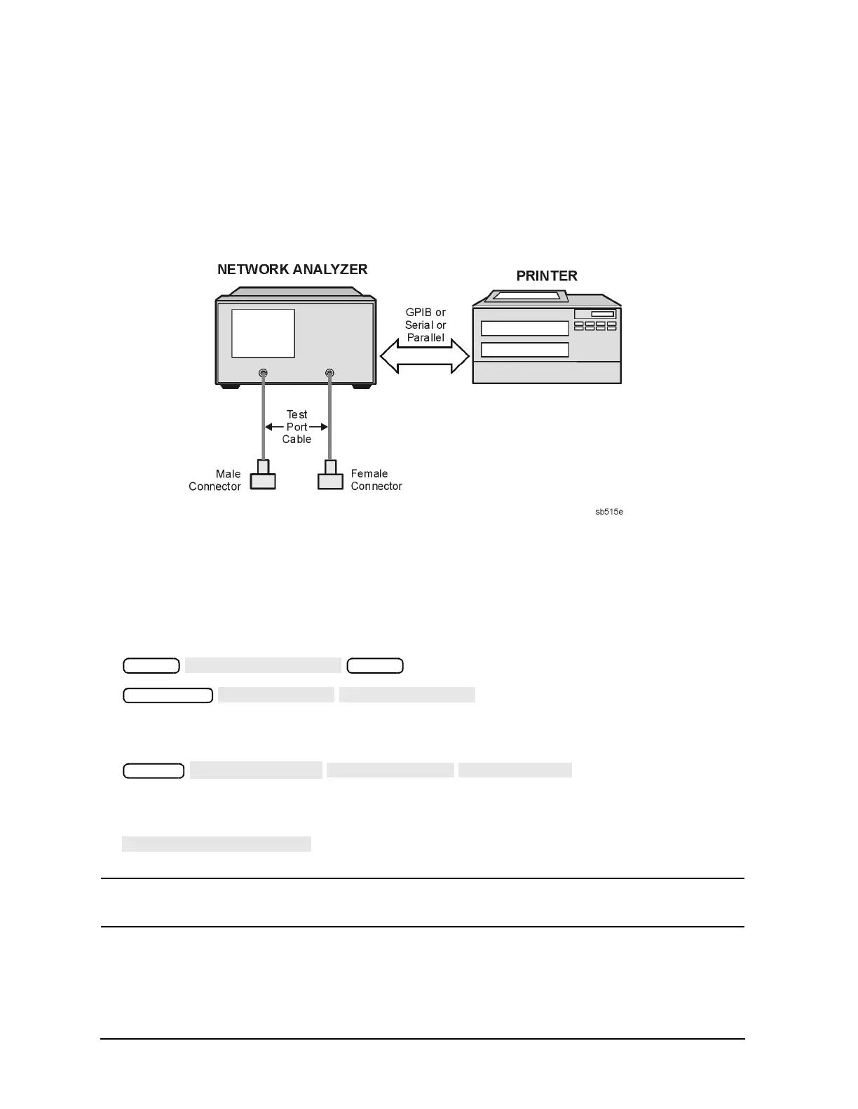
1. Connect a printer to the analyzer and cables to PORT 1 and PORT 2 (REFLECTION
port and TRANSMISSION port on ET models), as shown in Figure 2-8. Let the analyzer
warm up for at least 30 minutes. One cable should have a male connector and the other
a female connector.
Figure 2-8 System Verification Test Setup
2. While the equipment is warming up, review the “Principles of Microwave Connector
Care,” on page 1-6. Good connection technique with clean, undamaged connectors is
critical for accurate measurement results.
3. Insert the verification kit disk into the analyzer disk drive.
4. Press the following:
5. If you want a printout of the verification data in tabular form, as shown on page 2-32,
press the following:
If graphics (plots) of the display and a list are desired on the printout, as shown on
page 2-31 and page 2-32, press the following:
NOTE If you switch on the record function at this point, you cannot switch it off later
during the verification procedure.
6. Position the paper in the printer so that printing starts at the top of the page.
Preset
Preset
Save/Recall
System
 Loading...


