Service Guide 12-3
8719ET/20ET/22ET Theory of Operation
8719ES/20ES/22ES System Operation
RF Network Analyzers
System Operation
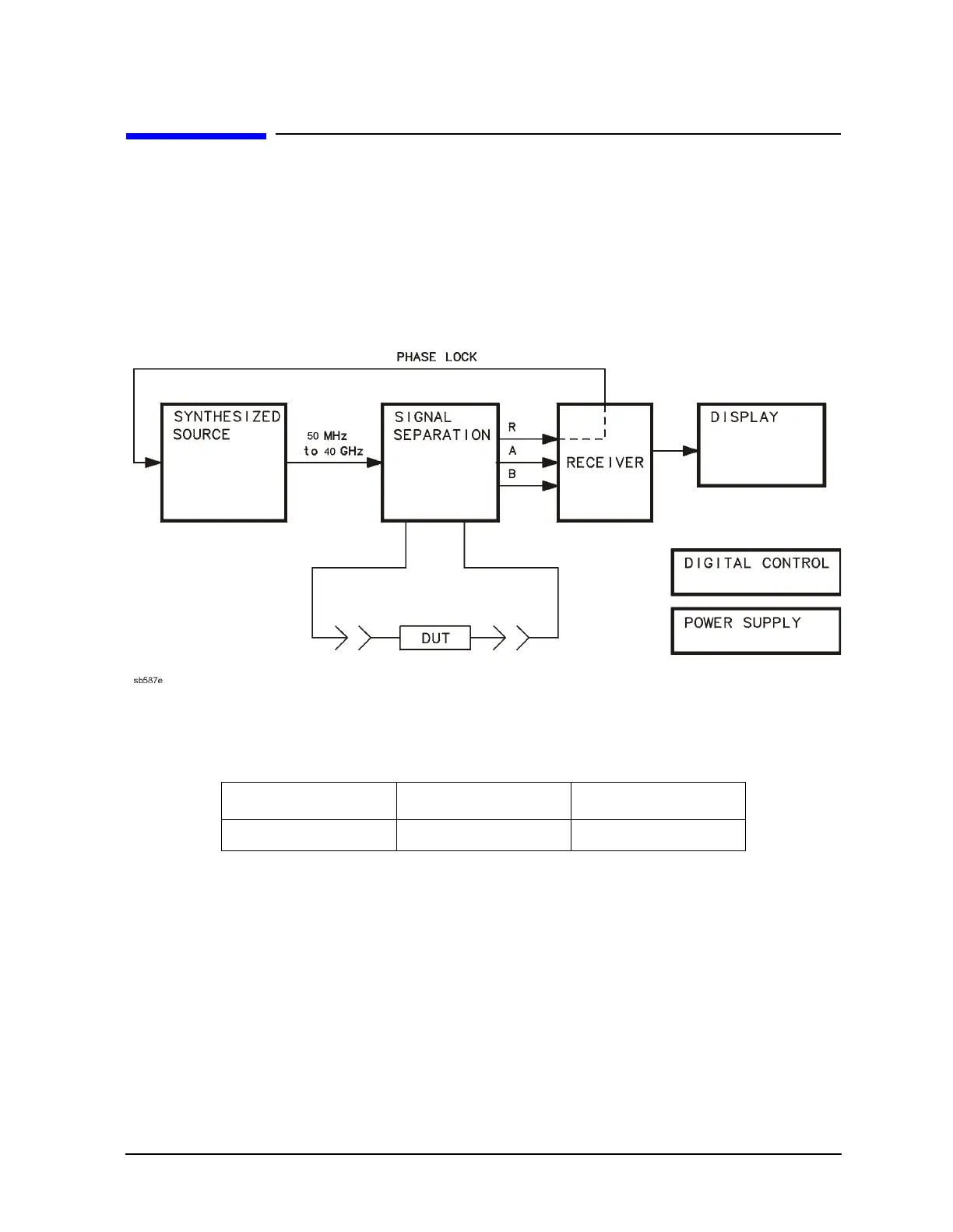
The 8719ET/ES, 8720ET/ES, and 8722ET/ES microwave network analyzers integrate a
synthesized source, signal separation devices, a three or four channel receiver for
measurement of test device characteristics, and a large-screen display. Figure 12-1 is a
simplified block diagram of the network analyzer system.
Figure 12-1 Simplified System Block Diagram
The built-in synthesized source of the analyzer generates a swept or continuous wave (CW)
signal in the following ranges:
The source output power is leveled by an internal ALC (automatic leveling control) circuit.
The output maximum power levels at the front panel are listed in Table 12-1 on page 12-4.
A portion of the source signal is routed to the R sampler receiver, and fed back to the
source for phase lock.
8719ET/ES 8720ET/ES 8722ET/ES
50 MHz to 13.51 GHz 50 MHz to 20.05 GHz 50 MHz to 40.05 GHz
 Loading...


