12-16 Service Guide
Theory of Operation 8719ET/20ET/22ET
Source Group Theory 8719ES/20ES/22ES
RF Network Analyzers
A12 Reference: The Crystal Reference Frequencies
This assembly provides stable reference frequencies to the rest of the instrument by
dividing down the output of a 40 MHz VCXO (voltage-controlled crystal oscillator). One of
the divided-down signals is the 100 kHz FN REF for phase locking the synthesizer signal
in A13. Another is the 1 MHz main phase-locked loop reference signal PL REF that goes to
the phase comparator in A11. (The 2nd LO signal and the timing signal for the A10 digital
IF assembly are explained in “Signal Separation: ES Models Only” on page 12-19.) The
EXT REF rear panel input provides the option of using an external reference with a
frequency of 1, 2, 5, or 10 MHz, instead of the internal 40 MHz VCXO.
Source Block: The YIG Oscillator Signals
The source block includes two YIG oscillators and a 3.8 GHz fixed oscillator. The outputs of
these oscillators produce the source signal. In phase-locked operation, this signal tracks
the stable output of the synthesizer. Figure 12-4 illustrates the assemblies in the source
block.
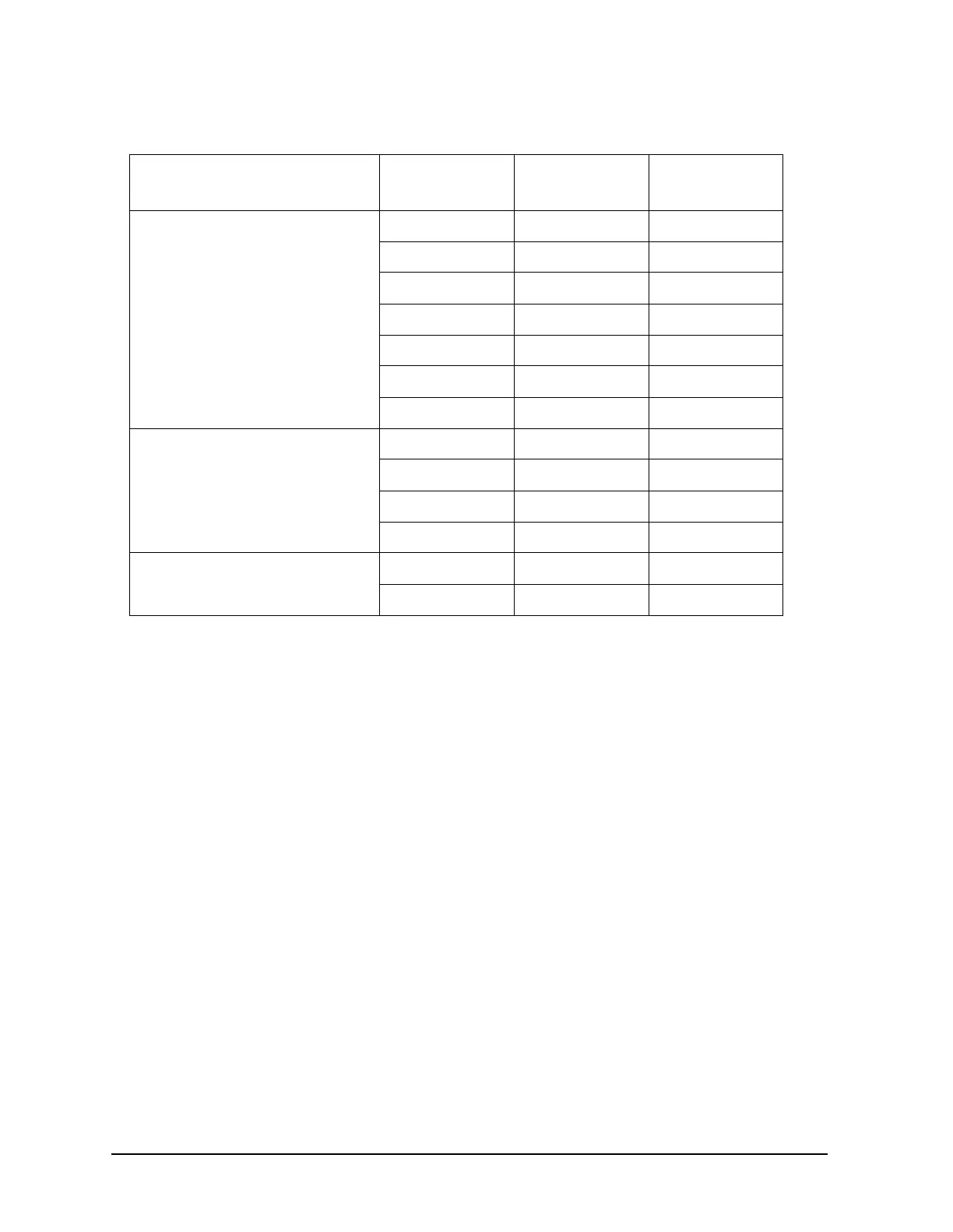
Table 12-2 Subsweep Frequencies
Band Synthesizer
(MHz)
Harmonic
Number (N)
Source (MHz)
Frequency
Low 60 to 120 1 50 - 110
120 to 240 1 110 - 230
120 to 240 2 230 - 470
160 to 236 3 470 - 698
141.6 to 236 5 698 - 1170
147.5 to 236 8 1170 - 1878
157.3 to 213.3 12 1878 - 2550
High Mid (8722ET/ES) 128 to 236 20 2550 - 4710
131.1 to 220/6 36 4710 - 8256
142.5 to 234 58 8256 - 13562
159.7 to 235.4 85 13562 - 20000
High (8722ET/ES) 178.7 to 223.3 112 20000 - 25000
148.9 to 238.2 168 25000 - 40000
 Loading...


