12-20 Service Guide
Theory of Operation 8719ET/20ET/22ET
Signal Separation: ES Models Only 8719ES/20ES/22ES
RF Network Analyzers
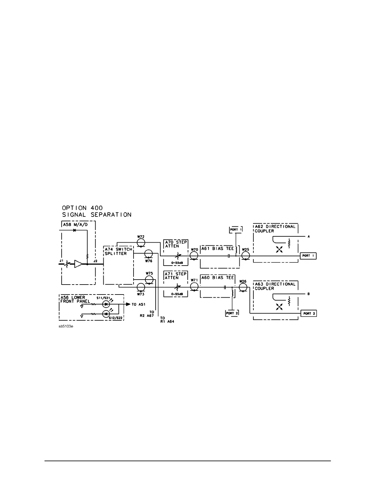
A58 M/A/D and A74 Switch Splitter (Option 400 Only)
The M/A/D (Modulator/Amplifier/Detector) microcircuit accomplishes three functions:
The modulator controls the output power proportionally to the signal produced by the ALC
circuit on the source interface board.
The amplifier can provide +30 dB of amplification. For maximum PORT 1 and PORT 2
output power levels, refer to Table 12-1 on page 12-4.
The detector outputs a voltage that is proportional to the RF power out of the amplifier.
The voltage is used by the ALC circuit on the source interface board.
The switch splitter (A74) divides three inputs:
• a path routed directly to A64 (R1 sampler)
• a path routed directly to the A67 (R2 sampler)
• a path switched to the appropriate output port (through A70/71 step attenuators,
A60/61 bias tees, and A62/63 directional couplers)
Figure 12-6 Option 400 Signal Separation Simplified Block Diagram
A69 Step Attenuator
The step attenuator provides coarse power control for the source signal. It is an
electro-mechanical attenuator, controlled by the A7 CPU, that provides 0 to 55 dB of
attenuation in 5 dB steps. It adjusts the power level to the device under test (DUT) without
changing the level of the incident power in the reference path.
 Loading...


