Service Guide 6-5
8719ET/20ET/22ET Digital Control Troubleshooting
8719ES/20ES/22ES CPU Board (A7) Troubleshooting
RF Network Analyzers
Checking the CPU (A7) Red LED Patterns
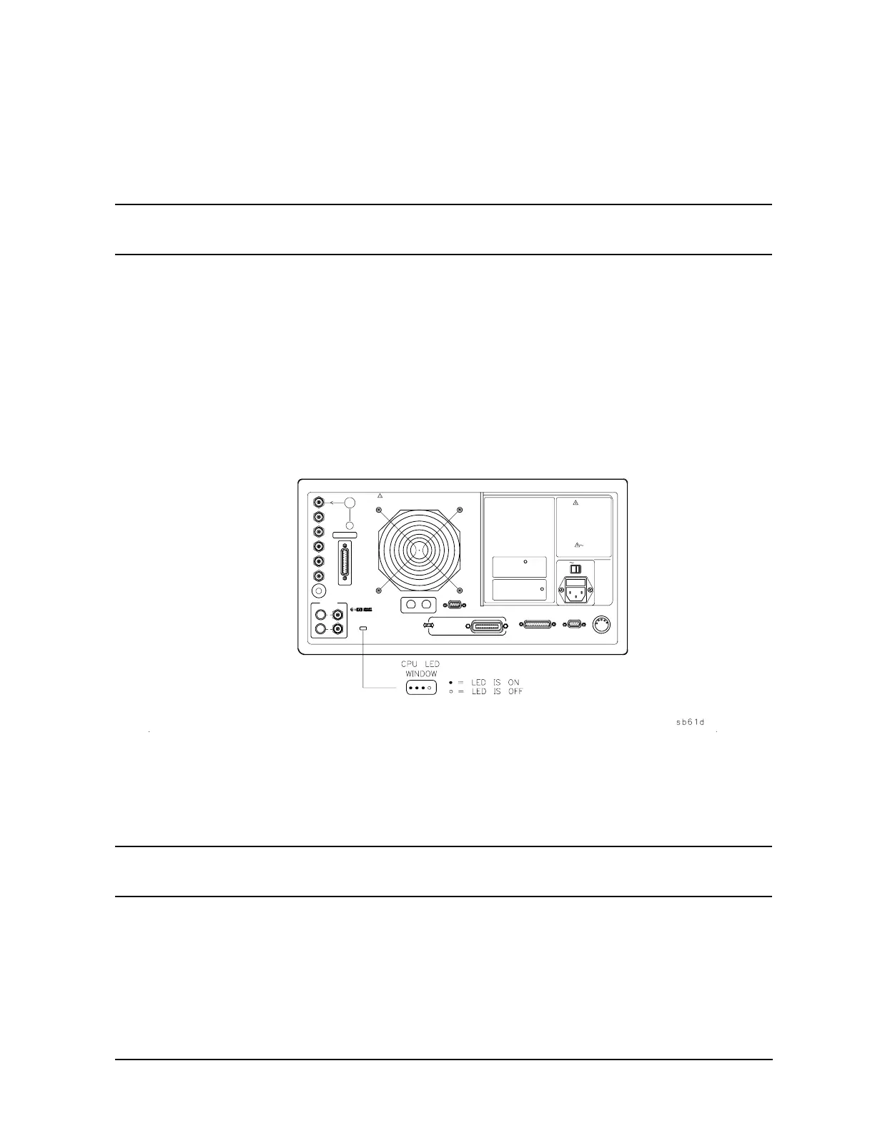
The CPU board (A7) has five (of eight) red LEDs that can be viewed through a small
opening in the rear panel of the analyzer (see Figure 6-2).
NOTE Four of the eight LEDs are easily viewed. The fifth LED can be viewed by
looking into the opening at a left angle.
1. Cycle the power while observing the five red LEDs.
Cycle the power on the analyzer and observe the five red LEDs. After an initial pattern,
the five LEDs on the CPU board (A7) should remain off.
• If the LEDs remained off, then proceed to the assembly that you suspect has a
problem.
• If the LEDs did not remain off, switch off the power and remove the bottom cover for
further troubleshooting.
Figure 6-2 CPU LED Window on Rear Panel
2. Cycle the power while observing all eight red LEDs.
With the analyzer positioned bottom up, cycle the power and observe the eight red
LEDs while looking from the front of the instrument.
NOTE If firmware did not load, a red LED on the CPU board will be flashing.
Refer to “Loading Firmware” on page 3-36.
 Loading...


