5-16 Service Guide
Power Supply Troubleshooting 8719ET/20ET/22ET
If the Green LEDs of the Post Regulator (A8) Are Not All ON 8719ES/20ES/22ES
RF Network Analyzers
5. Of those assemblies that are left on the list, remove or disconnect them from the
analyzer one at a time. Table 5-4 on page 5-16 shows the best order in which to remove
them, sorting them from most to least accessible. Table 5-4 also lists any associated
assemblies that are supplied by the assembly that is being removed. After each
assembly is removed or disconnected, switch on the analyzer and observe the LEDs.
• If all the LEDs light, the assembly removed (or one receiving power from it) is faulty.
• If the LEDs are still not on steadily, continue with the next section “Inspect the
Motherboard.”
Inspect the Motherboard
Inspect the motherboard (A17) for solder bridges and shorted traces. In particular, inspect
the traces that carry the supplies whose LEDs faulted when A8TP4 (SDIS) was grounded
earlier.
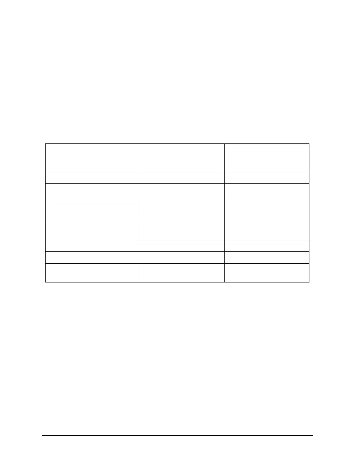
Table 5-4 Recommended Order for Removal/Disconnection for Troubleshooting
the A8 Board
Assembly to Remove Removal or Disconnection
Method
Other Assemblies That
Receive Power from the
Removed Assembly
1. CPU Board (A7) Disconnect W87 None
2. R Sampler (A4) Unplug from A17 and
Remove
None
3. A Sampler (A5) Unplug from A17 and
Remove
None
4. B Sampler (A6) Unplug from A17 and
Remove
None
5. Source Control (A9) Disconnect W91 None
6. Front Panel Interface (A2) Disconnect W84 Front Panel Keyboard (A1)
7. Test Set Interface (A51) Disconnect W89 Transfer Switch (S4)
LED Front Panel (A56)
 Loading...


