6-4 Service Guide
Digital Control Troubleshooting 8719ET/20ET/22ET
CPU Board (A7) Troubleshooting 8719ES/20ES/22ES
RF Network Analyzers
CPU Board (A7) Troubleshooting
A7 Switch Positions
The A7 switch position must be in the Normal position (NRM) for these procedures. This is
the position for normal operating conditions. To move the switch to the Normal position
(NRM) position, do the following:
NOTE Before moving the A7 switch, perform “EEPROM Backup Disk Procedure” on
page 3-33 to save your correction constants.
1. Remove the power line cord from the analyzer.
2. Set the analyzer on its side.
3. Remove the two corner bumpers from the bottom of the instrument with a T-15 TORX
screwdriver.
4. Loosen the captive screw on the bottom cover's back edge.
5. Slide the cover toward the rear of the instrument.
CAUTION Be sure to observe proper ESD procedures and precautions when performing
the following step.
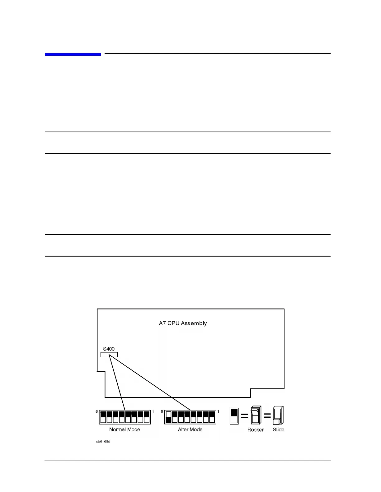
6. Move the switch to the Normal position (NRM) as shown in Figure 6-1.
7. Replace the bottom cover, corner bumpers, and power cord.
Figure 6-1 Jumper Positions on the CPU (A7)
 Loading...


