4-24 Service Guide
Start Troubleshooting Here 8719ET/20ET/22ET
Receiver Check 8719ES/20ES/22ES
RF Network Analyzers
Checking the B Channel Output (ET and ES Models)
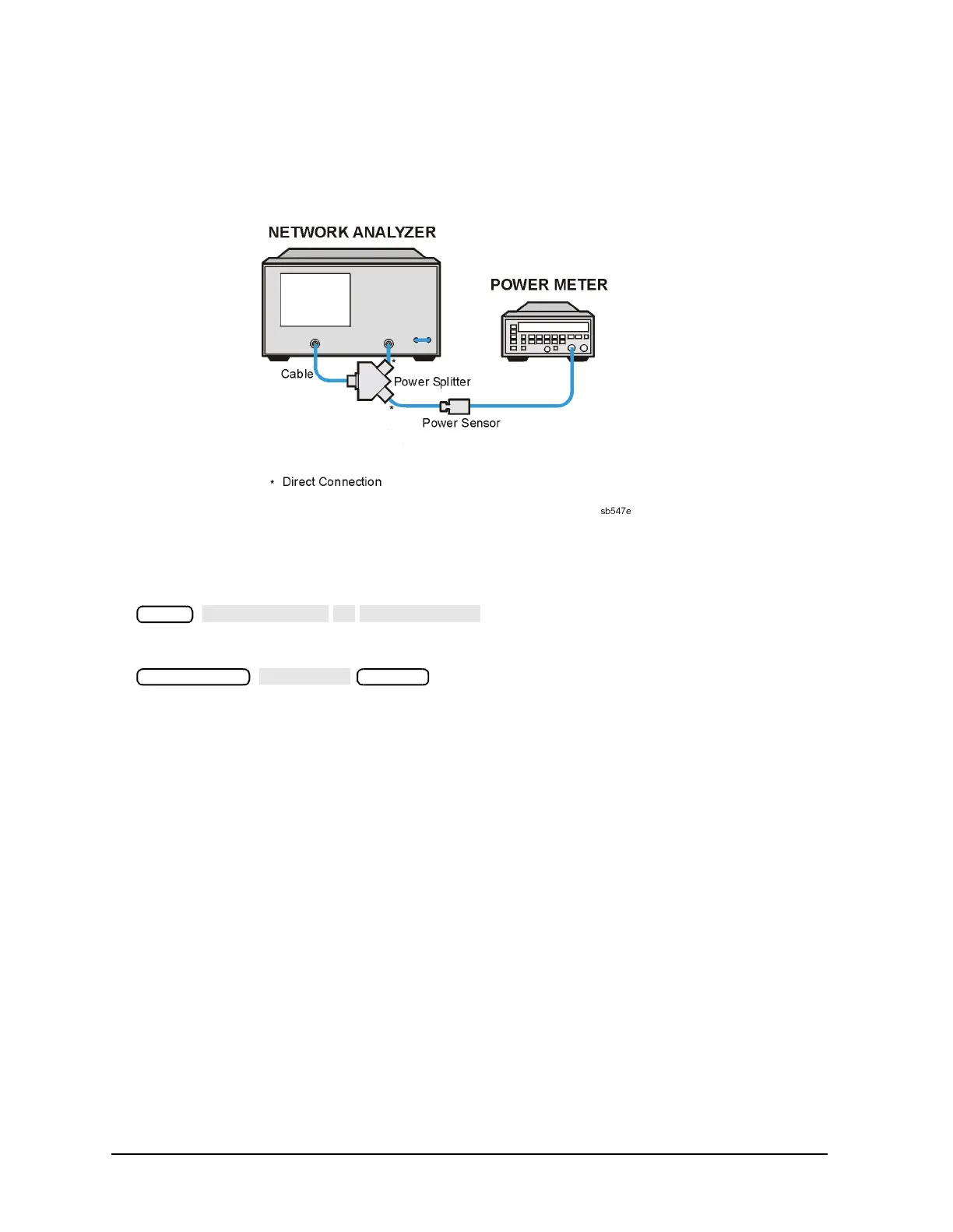
13.Connect the equipment as shown in Figure 4-9.
Figure 4-9 Setup for the B Channel Receiver Check (ES Models)
14.Zero and calibrate the power meter.
15.Press the following:
16.Press the following:
17.Calculate the difference between the power meter reading and the marker reading on
the analyzer display. This power difference is the frequency response of the B channel.
18.Repeat steps 16 and 17 at the frequency points where a problem is suspected or check
different frequency points across the band (set the calibration factor on the power meter
for each frequency measured). For the characteristic values of the frequency response,
see Table 4-3 on page 4-21.
In Case of Difficulty
• Make sure the power meter and power sensor are operating correctly.
• Enter the exact power meter calibration factor for the frequencies that are failing. Refer
to the power meter user’s guide.
• Measure the RF power splitter tracking and the cable loss. Account for these losses in
the frequency response calculations.
Meas
 Loading...


