14-34 Service Guide
Assembly Replacement and Post-Repair Procedures 8719ET/20ET/22ET
Removing the B1 Fan Assembly 8719ES/20ES/22ES
RF Network Analyzers
Removing the B1 Fan Assembly
Tools Required
• 2.5-mm hex-key driver
• T-10 TORX screwdriver
• T-15 TORX screwdriver
• ESD (electrostatic discharge) grounding wrist strap
Removal
1. Remove the rear panel; refer to “Removing the Rear Panel Assembly” on page 14-14.
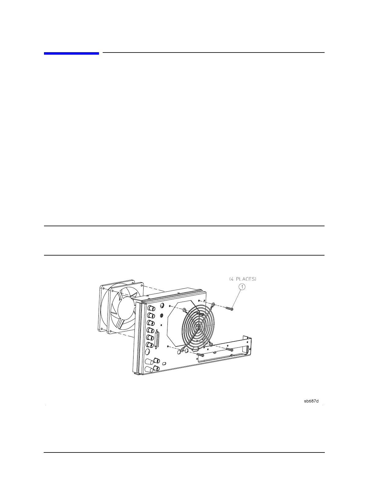
2. Remove the 4 screws (item 1) that secure the fan and fan cover to the rear panel.
Replacement
1. Reverse the order of the removal procedure.
NOTE The fan should be installed so that the direction of the air flow is away from
the instrument. There is an arrow on the fan chassis indicating the air flow
direction.
 Loading...


