Service Guide 7-17
8719ET/20ET/22ET Source Troubleshooting
8719ES/20ES/22ES Broadband Phase Lock Problems
RF Network Analyzers
4. Turn on the analyzer.
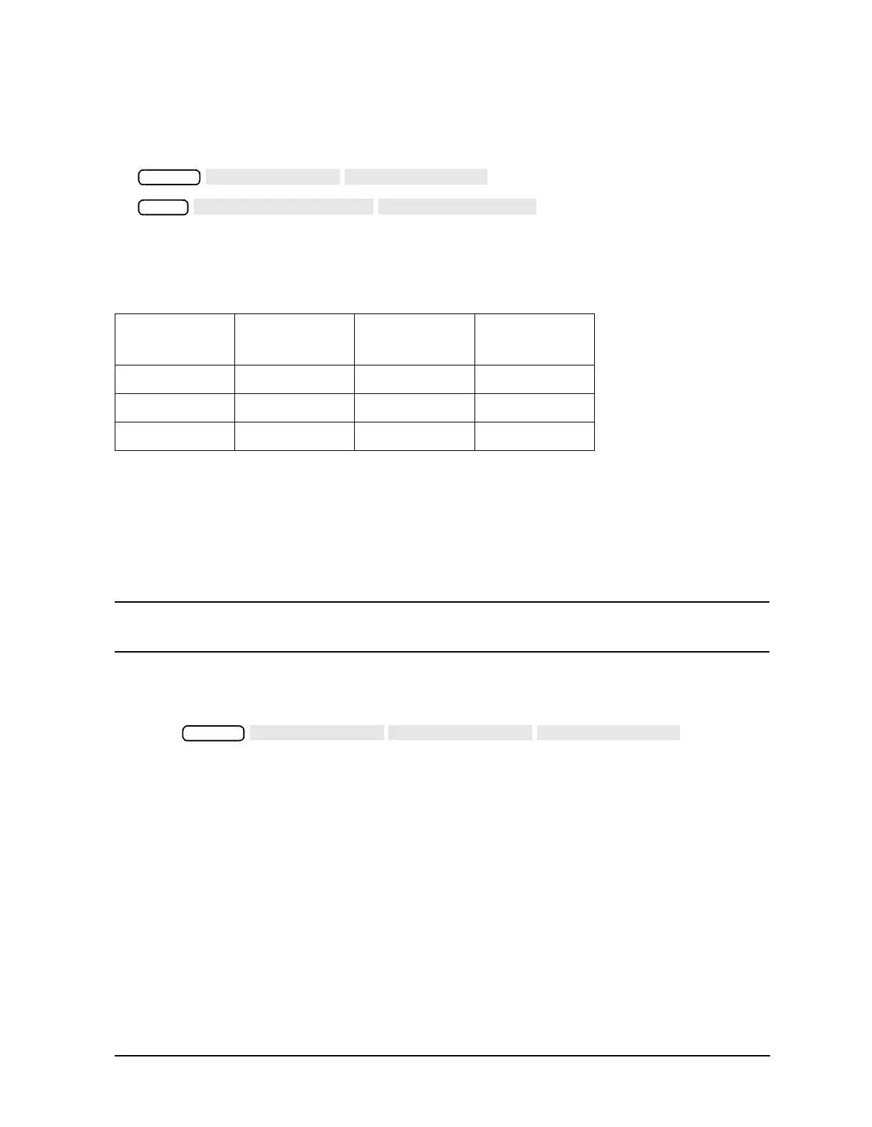
5. To set the internal counter to the frac-N node, press the following:
6. In turn, jumper each of the three supply voltages to A14TP14 and observe the frequency
as shown in Table 7-2. A variation of ±10% is expected. The counter frequency needs to
be extremely out of specification to constitute a failure.
7. If the frequency changes are not correct, replace A14.
8. If the frequency changes are correct, continue with “Divide-by-N (A14) Circuit Check”
next.
Divide-by-N (A14) Circuit Check
NOTE The A13 assembly should still be out of the instrument and the A14 assembly
on an extender board.
1. Jumper A14TP14 to the +5VU supply.
2. Connect an oscilloscope to A14J3 (labeled VCO/N OUT).
3. Press .
4. Vary the fractional-N frequency from 120 MHz to 242 MHz.
• If the period of the signal does not vary from 7.5 µsec to 15.5 µsec, replace A14. A
variation of ±10% is expected. The counter frequency needs to be extremely out of
specification to constitute a failure.
• If the period does vary as prescribed, remove the jumper and reinsert A14. Always
turn off the analyzer before removing or replacing any assembly.
A14-to-A13 Digital Control Signals Check
1. Place A13 on the extender board and reconnect all of the flexible cables (the one to
A14J1 is optional).
2. The A14 assembly generates a TTL cycle start (CST) signal every 10 microseconds
when the VCO is oscillating.
Table 7-2 VCO Exercise Matrix
Supply Test
Point
Voltage
Mnemonic
A14 Test Point Counter
Frequency
A8TP7 +15V A14TP14 ≅ 240 MHz
A8TP8 +5VU A14TP14 ≅ 155 MHz
A8TP2 AGND A14TP14 ≅ 105 MHz
System
Meas
System
 Loading...


