7-18 Service Guide
Source Troubleshooting 8719ET/20ET/22ET
Broadband Phase Lock Problems 8719ES/20ES/22ES
RF Network Analyzers
3. Connect an oscilloscope to A14TP3 (CST). (Suggested vertical scale: 2.0V/div.)
4. Press to stop the sweep. This will make
triggering on these waveforms easier.
5. If there is no signal, replace A14.
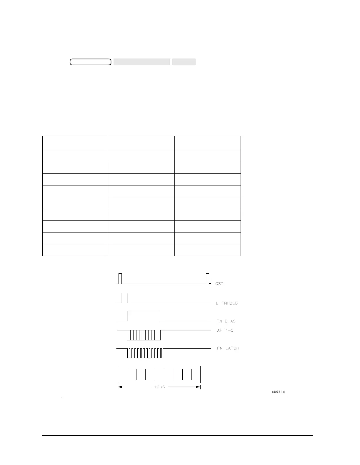
6. Use the CST signal as an external trigger for the oscilloscope and observe the signals
listed in Figure 7-4. Since these TTL signals are generated by A14 to control A13, check
them at A13 first.
The signals should look similar to the waveforms in Figure 7-4.
Figure 7-4 A14 TTL Signals at A14TP3
• If these signals are bad, replace A14. If the signals are bad, replace A13.
Table 7-3 A14-to-A13 Digital Control Signal Locations
Mnemonic A13 Location A14 Location
CST none TP3
L FNHOLD P2-2 P2-2
FNBIAS P2-5 P2-5
API1 P2-32 P2-32
API2 P2-3 P2-3
API3 P2-34 P2-34
API4 P2-4 P2-4
API5 P2-35 P2-35
FNLATCH P1-28 P1-58
 Loading...


