7-22 Service Guide
Source Troubleshooting 8719ET/20ET/22ET
Band-Related Problems 8719ES/20ES/22ES
RF Network Analyzers
Band-Related Problems
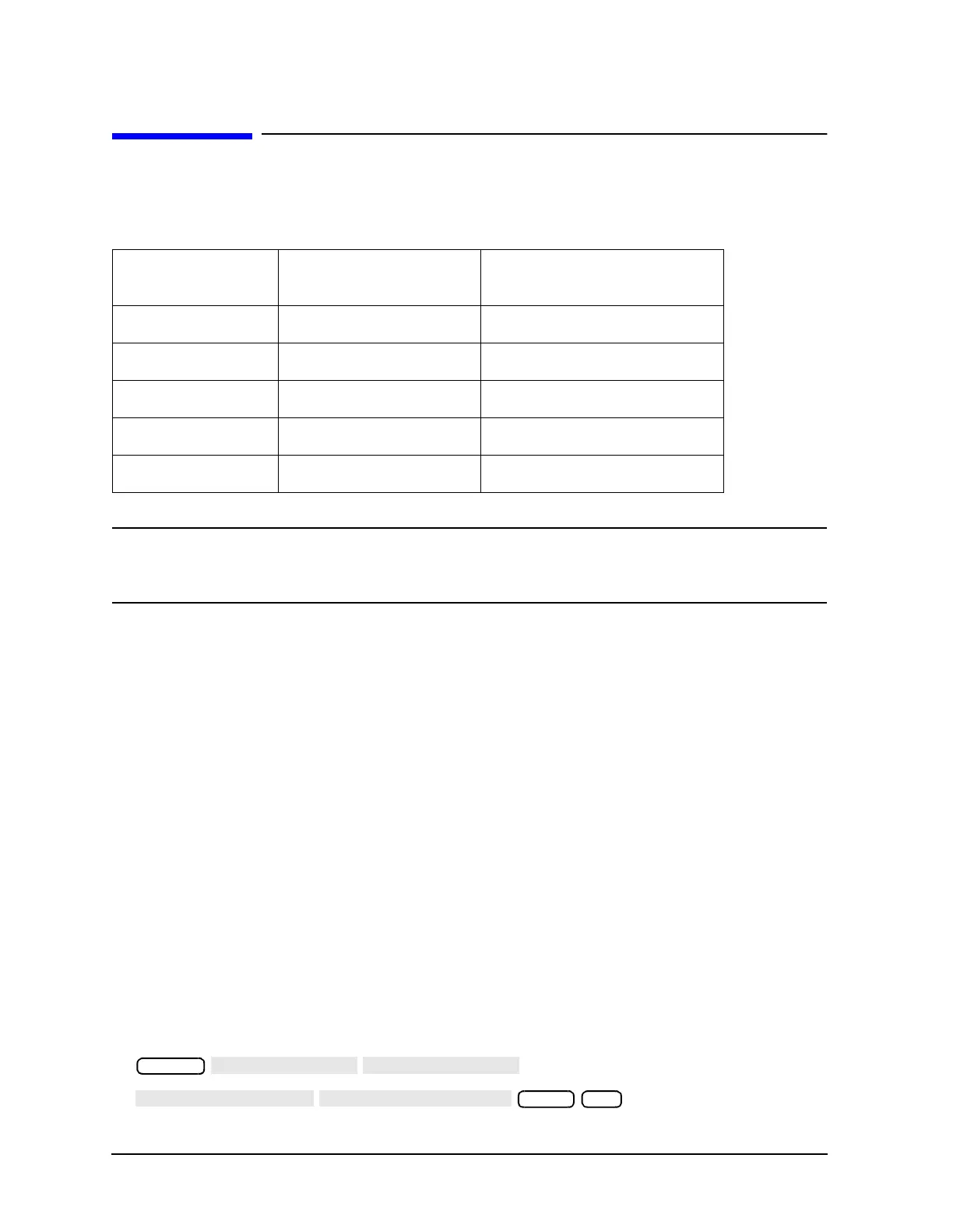
Table 7-5 lists assemblies potentially responsible for band-related problems.
NOTE Problems in RF components, crimped RF cables, and improper connections
which generally cause power holes in an RF signal may cause symptoms that
indicate a band-related problem.
Start by measuring power at A5J3 (source switch) (A25J3 switch, 8722ET/ES only). If the
power here is good, then all of the band related components are verified. To check other
components, continue troubleshooting with “Broadband Power Problems” on page 7-26.
Keep the following points in mind.
• Remove the instrument covers.
• Cables having improper connections can be the problem in all cases.
• Use the flexible RF cable from the tool kit to measure power at otherwise inaccessible
connections.
• Before replacing suspect assemblies, check bias voltages on A54 (YIG oscillator),
A55 (YIG oscillator), and A57 (cavity oscillator).
— A54 and A55: +22 V middle pin, +15 V left pin on J1.
— A57: +20 V left pin, −10 V right pin.
Low Band Problems:
1. Calibrate and zero a power meter and connect it to A5J3 on ET models (A25J3 for
8722ET/ES).
2. To measure power at J3, press the following:
Table 7-5 Assemblies Potentially Responsible for Band-Related Problems
Low Band Mid Band
(8722ET/ES Only)
High Band
A57
A55 A59
A53
A5 (source switch) A5 (source switch)
A5 (source switch)
A6 (source switch) A6 (source switch)
A6 (source switch)
A59 A25 switch (8722ET/ES)
A59
A54 (8722ET/ES)
System
4000 x1
 Loading...


