5-6 Service Guide
Power Supply Troubleshooting 8719ET/20ET/22ET
Start Here 8719ES/20ES/22ES
RF Network Analyzers
Start Here
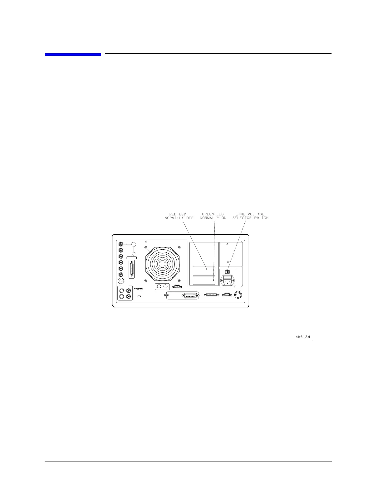
Check the Green LED and Red LED on the Preregulator (A15)
Switch on the analyzer and look at the rear panel of the analyzer. Check the two power
supply diagnostic LEDs on the preregulator (A15) casting by looking through the holes
located to the left of the line voltage selector switch (see Figure 5-2).
During normal operation, the bottom (green) LED is on and the top (red) LED is off. If
these LEDs are normal, then A15 is 95% verified. Proceed to the next section “Check the
Green LEDs on the Post Regulator (A8).”
• If the green LED is not on steadily, refer to “If the Green LED of the Preregulator (A15)
Is Off or Blinking” on page 5-8.
• If the red LED is on or flashing, refer to “If the Red LED of the Preregulator (A15) Is
On” on page 5-9.
Figure 5-2 Location of the Pregulator (A15) Diagnostic LEDs
Check the Green LEDs on the Post Regulator (A8)
Remove the top cover of the analyzer and locate the post regulator (A8); use the location
diagram under the top cover if necessary. Check to see if the green LEDs on the top edge of
A8 are all on. There are nine green LEDs (one is not visible without removing the PC board
stabilizer).
• If all of the green LEDs on the top edge of A8 are on, there is a 95% confidence level that
the power supply is verified. To confirm the last 5% uncertainty of the power supply,
continue to the next section “Measure the Post Regulator (A8) Voltages.”
• If any LED on A8 is off or flashing, refer to “If the Green LEDs of the Post Regulator
(A8) Are Not All ON” on page 5-13.
 Loading...


