168 Maintaining Your GC
9 Maintaining the PTV Inlet
5
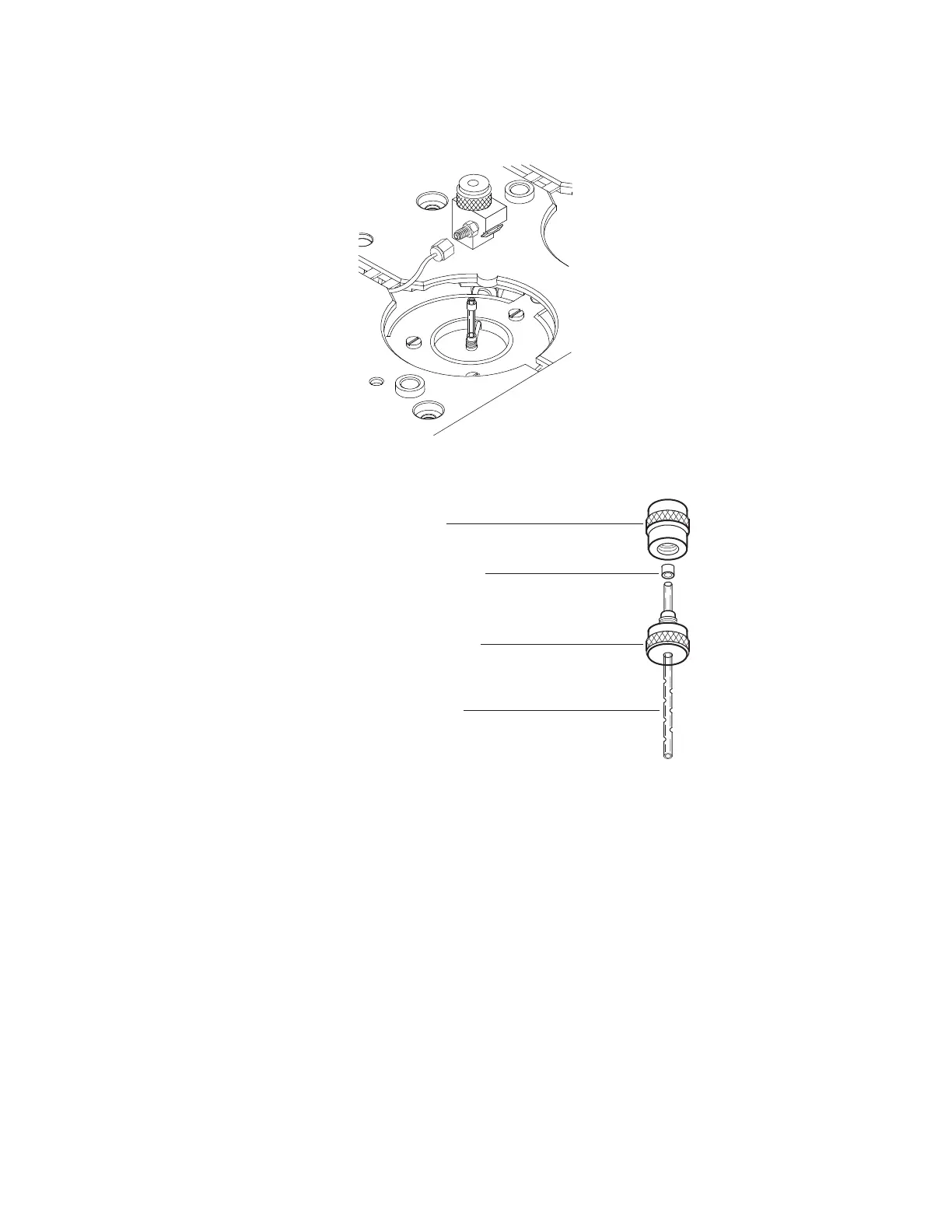
Unscrew the assembly tool into two pieces: the ferrule
guide and the compression fitting.
6 Slide the compression fitting onto the longer, straight end
of the new liner with the threads pointing toward the end
of the liner.
7 Place a Graphpak 3D ferrule on the same end of the liner
with the recessed graphite end towards the compression
fitting. Slide the ferrule so that about 2 mm of the liner is
exposed beyond the ferrule.
8 Slide the compression fitting up to meet the ferrule.
Finger- tighten the ferrule guide onto the compression
fitting.
9 Unscrew and remove the ferrule guide.
10 Slide the compression fitting off the other end of the
liner. The ferrule should now be set with 1 mm of the
liner exposed. Check that the graphite within the ferrule
is flush with the top of the metal collar.
Ferrule guide
Graphpak 3D ferrule
Compression fitting
Open baffle liner
 Loading...