346 Maintaining Your GC
19 Maintaining a Valve
To Install the Upper Valve Box
1 Gather the following:
• T- 20 Torx screwdriver
• 3- mm hex key wrench
• Flathead screwdriver
2 Verify that all valve rotors are in the full counterclockwise
position (valve Off).
3 For each actuator that mates with a newly installed valve:
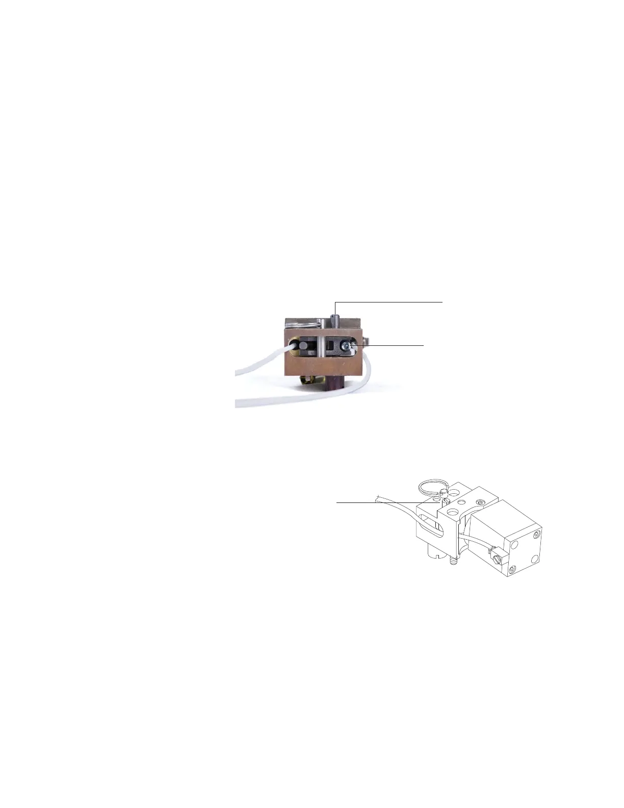
a Loosen the adjustment set screw.
b Locate the rotor adjustment shaft on top of the
actuator. Use a screwdriver to rotate the valve rotor
counterclockwise until it stops.
4 Locate the two half- moon cutouts at the bottom back of
the upper valve box. Place the upper valve box on top of
the lower valve assembly, routing the heater/sensor wires
through the cutouts. Secure with two T- 20 mounting
screws.
5 Push each coupling/shaft assembly downward with a
flathead screwdriver until the slot on the coupling
engages the rotor index pin.
If the coupling and valve do not engage, check that both
are fully counterclockwise and try again. If necessary,
turn the shaft slightly to engage the coupling.
Rotor adjustment
slotted shaft
Adjustment set screw
 Loading...