Maintaining the VI 10
Maintaining Your GC 183
8
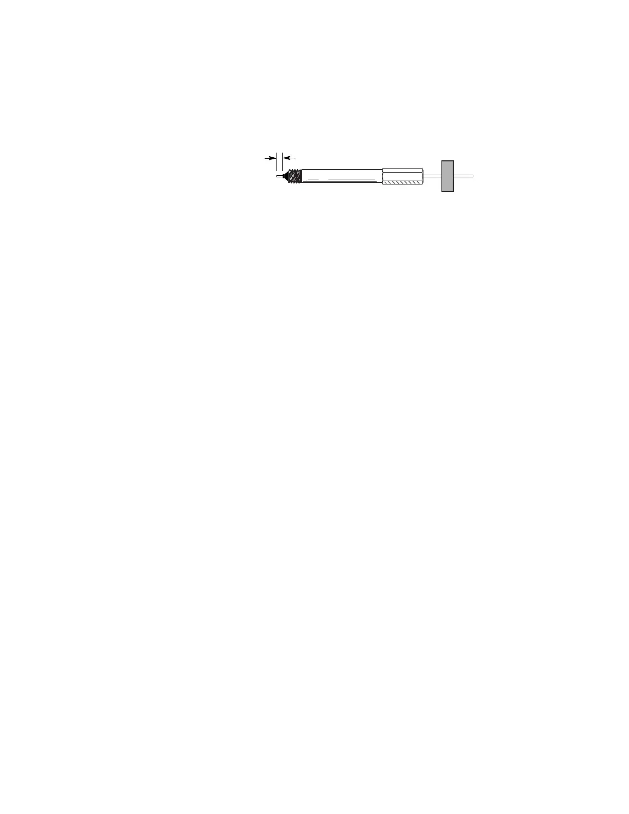
Position the column so it extends 6 mm above the end of
the ferrule. Slide the septum up the column to hold the
column nut at this fixed position.
9 Insert the column into the interface and finger- tighten the
column nut.
10 Adjust the column (not the septum) position until the
septum is snug against the bottom of the nut.
11 Tighten the column nut an additional 1/4 to 1/2 turn with
a wrench so that the column cannot be pulled from the
fitting with gentle pressure.
12 Configure the new column. If using the optional barcode
scanner, scan the column directly into your data system
software configuration, then download the changes to the
GC.
13 With the sample transfer line attached and the column
attached to the inlet and detector, establish a flow of
carrier gas through the transfer line. Purge as
recommended by the column manufacturer.
14 Condition the column per the manufacturer’s
recommendation. (See To Condition a Capillary Column.)
15 Install the column into the detector. See:
• To Install a Capillary Column in the FID
• To Install a Capillary Column in the NPD
• To Install a Capillary Column in the TCD
• To Install a Capillary Column in the uECD
• To install a Capillary Column in the FPD Plus
• To Install a Capillary Column Adapter in the FPD
16 After the column is installed at both inlet and detector,
establish a flow of carrier gas and purge as recommended
by the column manufacturer.
17 Restore the analytical method.
• For FPD, immediately turn off the flame.
• For NPD, immediately set the bead voltage to 0.0.
18 After the GC becomes ready, wait 10 minutes then ignite
the detector flame or adjust offset on the NPD bead.
 Loading...