220 1100 Series WS MWS Reference Manual
7 Theory of Operation
Transport Unit Control
The transport drive electronics use current-controlled pulse-width modulation
(PWM) to drive the X, Z,
θ motors in closed-loop servo control mode.
Dedicated electronics in the ST L6506 provide the current-control loop.
Commutation is done in FPGA logic. The ST L6201 SMT output drivers are
used for all three stepper motors. Motor encoder signals are connected to the
ASIC where the encoder quadrature decoded clock and the up/down signal
are used in the FPGA to provide instantaneous stepper motor commutation
with respect to the motor rotor position.
Wiring between the well-plate sampler main board (ASM) and the motors and
encoders uses a flat-band cable (64 pin) and a flex board on which 13
reflection light sensors are located. 9 light sensors are used for vial-tray
identification and four for decoding of the initialization position.
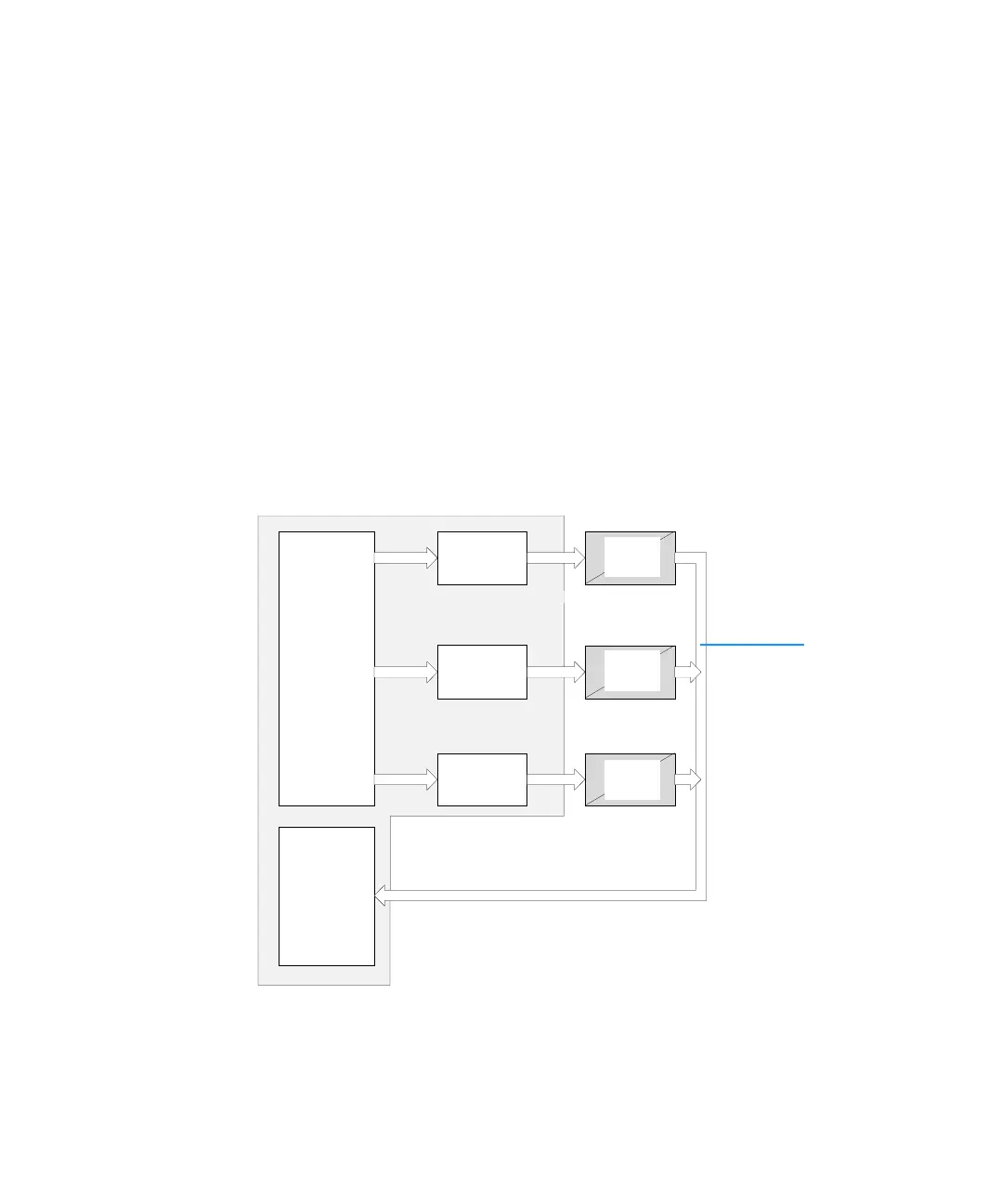
Figure 37 Transport unit control
FPGA
X-Axis Drive
.6 A / phase
ASIC
Motor
Encoder
Motor
Encoder
Motor
Encoder
Via
transport
unit flex
board
Reflection sensors on transport unit flex board:
Tray decoding (9), initialization sensors (4).
Z-Axis Drive
.6 A / phase
Theta Drive
.6 A / phase
 Loading...