Agilent 1290 Infinity Binary Pump User Manual 33
Installing the Module
3
Installing the Pump
3 Connect the power cable to the power connector at the back of the 1290
Infinity Binary Pump.
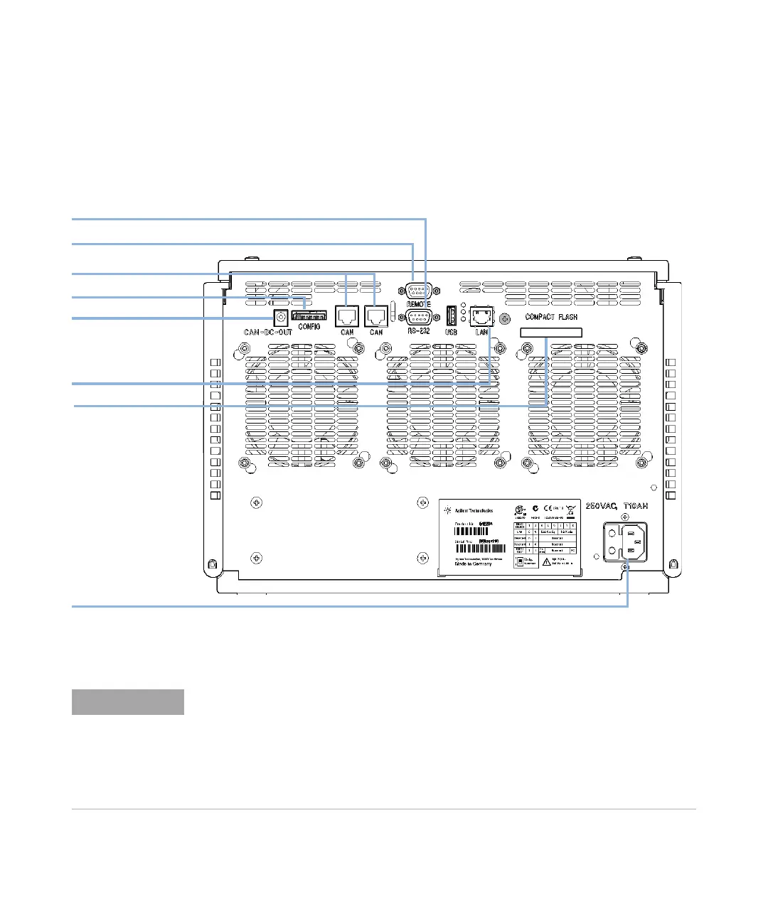
4 Connect the required interface cables to the rear of the 1290 Infinity Binary
Pump.
Figure 7 Rear of Binary Pump
8dc[^\jgVi^dchl^iX]
86C"7jh
GH'('
A6C
8dbeVXi;aVh]
EdlZgeaj\
6E<"GZbdiZ
EdlZghjeean[dgZmiZgcVa
86CkVakZh
In an Agilent 1290 Infinity System, the individual modules are connected by CAN cables. An
Agilent 1200 Series Instant Pilot can be connected to the CAN bus of any module.
Connection to an Agilent data system is established through the built-in LAN port of the
detector. The LAN port of the detector must be used as the detector generates the highest
data rate of all modules. For more information about connecting the Instant Pilot or Agilent
Data System, please refer to the respective user manual. For setting up the LAN access,
see “LAN Configuration” on page 223.