104 34410A/11A/L4411A User’s Guide
4 Measurement Tutorial
Resistance Measurement Considerations
The multimeter offers two methods for measuring resistance: 2–wire and
4–wire ohms. For both methods, the test current flows from the input HI
terminal and then through the resistor being measured. For 2–wire ohms, the
voltage drop across the resistor being measured is sensed internal to the
multimeter. Therefore, test lead resistance is also measured. For 4–wire ohms,
separate "sense" connections are required. Since no current flows in the sense
leads, the resistance in these leads does not give a measurement error.
The errors mentioned earlier in this chapter for dc voltage measurements
also apply to resistance measurements. Additional error sources unique to
resistance measurements are discussed on the following pages.
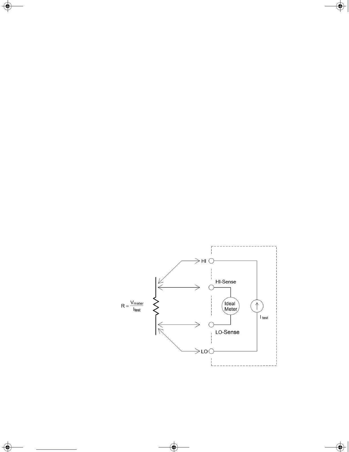
4–Wire Ohms Measurements
The 4–wire ohms method provides the most accurate way to measure small
resistances. Test lead resistances and contact resistances are automatically
reduced using this method. Four–wire ohms is often used in automated test
applications where resistive and/or long cable lengths, numerous connections,
or switches exist between the multimeter and the device–under–test. The
recommended connections for 4–wire ohms measurements are shown below.
See also “To Make a 4-wire Resistance Measurement” on page 20.
UG_ED5.book Page 104 Thursday, March 1, 2012 11:28 AM

 Loading...


