34410A/11A/L4411A User’s Guide 75
Features and Functions 2
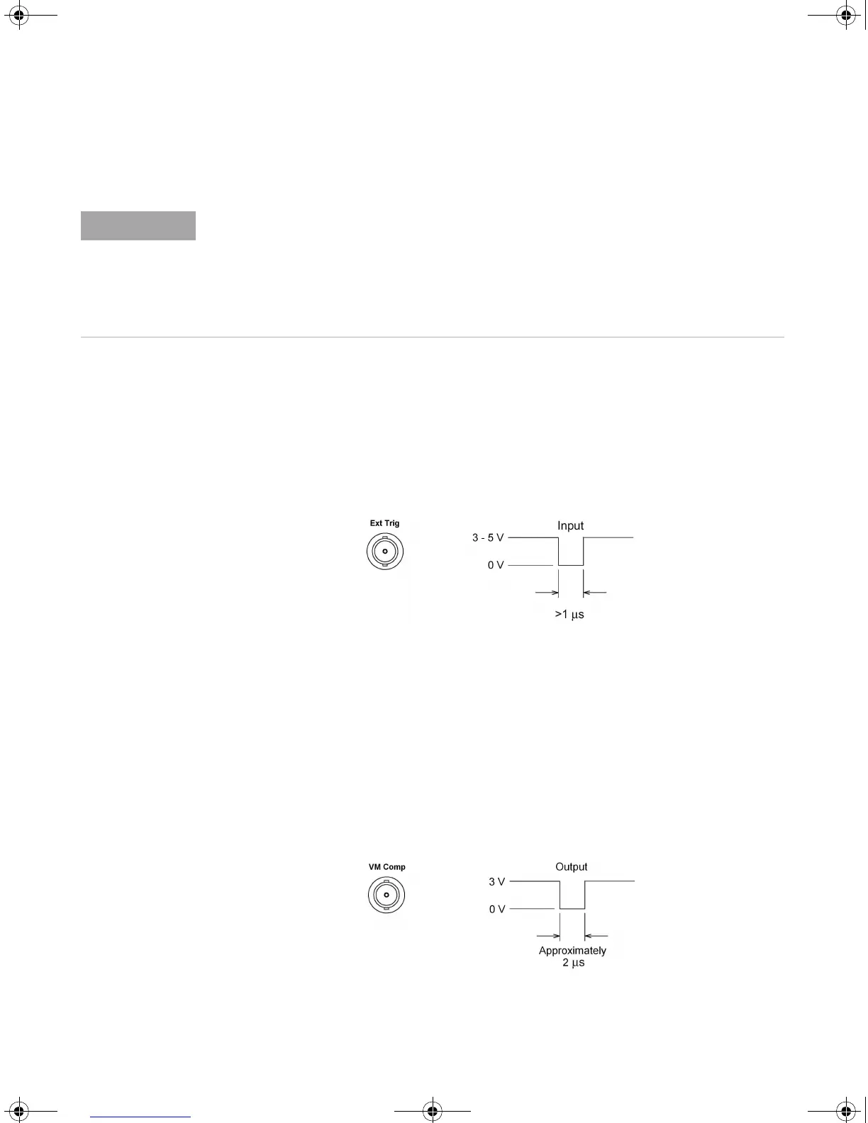
External Triggering
External triggering takes one reading (or the specified number of readings)
each time the multimeter receives a pulse on the rear–panel Ext Trig connector.
You may select whether the multimeter uses the rising edge (POS) or falling
edge (NEG) of the external trigger signal to trigger a reading (see “Trigger
Slope” on page 77). The diagram below shows the Ext Trig connector timing (for
a negative pulse).
• The multimeter buffers one external trigger. If the multimeter is currently
taking a reading while another trigger occurs, that second trigger is
accepted. After the reading in progress is completed, the stored trigger is
issued.
• The Trig annunciator turns on when the multimeter is waiting for an
external trigger.
• The rear panel VM Comp (voltmeter complete) connector provides a pulse
after completion of each measurement. Voltmeter complete and external
trigger implement a standard hardware handshake sequence between
measurement and switching devices. The diagram below shows the VM Comp
connector timing (for a negative pulse).
Temperature is measured using the 2–wire or 4–wire resistance function. The above tables
for resistance apply to temperature, but all temperature measurements use autoranging.
The range in use cannot be predicted; thus, nor can the delay. Use the TRIGger:DELay?
command to query the actual trigger delay for a temperature measurement.
For capacitance measurements the automatic trigger delay is zero (capacitor discharge is
part of the measurement). The continuity and diode test functions ignore the trigger delay.
UG_ED5.book Page 75 Thursday, March 1, 2012 11:28 AM
 Loading...


