34410A/11A/L4411A User’s Guide 73
Features and Functions 2
If the multimeter is configured to take more than one sample per trigger,
the effect of the trigger delay on subsequent samples depends on the sample
source setting. Refer to the SAMPle:SOURce command description in the
Agilent 34410A/11A/L4411A Programmer’s Reference Help for a detailed
description.
After setting the trigger delay, you must use the INITiate or READ
command to place the meter in the wait–for–trigger state before readings
are triggered (see “Software (Bus) Triggering” on page 70). The MEASure?
command sets the trigger delay to AUTO.
Refer to the Agilent 34410A/11A/L4411A Programmer’s Reference Help for
a complete description and syntax for these command.
Automatic Trigger Delay
If you do not specify a trigger delay, the multimeter selects the trigger delay
time automatically. Automatic trigger delays are set to ensure that completely
settled and accurate measurements are taken. The delay is determined by
function, range, integration time, and ac filter setting.
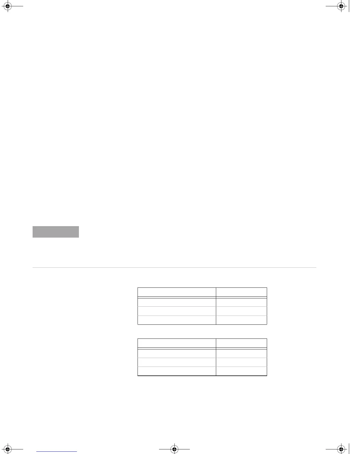
DC Voltage Measurements (all ranges):
DC Current Measurements (all ranges):
For measurements from the remote interface, the automatic trigger delay values are as
shown in the tables that follow. These values are also used for single-trigger, reading-hold,
and level-trigger measurements from the front panel. However, for auto-trigger
measurements from the front panel only, the automatic trigger delay is 50 ms for all
measurement functions.
Integration Time Trigger Delay
≥ 1 PLC 160 μs
0.06 PLC or 0.2 PLC 130 μs
≤ 0.02 PLC 100 μs
Integration Time Trigger Delay
≥ 1 PLC 1.5 ms
0.06 PLC or 0.2 PLC 1.0 ms
≤ 0.2 PLC 1.0 ms
UG_ED5.book Page 73 Thursday, March 1, 2012 11:28 AM
 Loading...


