Frequency and Time Domain Analysis 6
U8903A User’s Guide 111
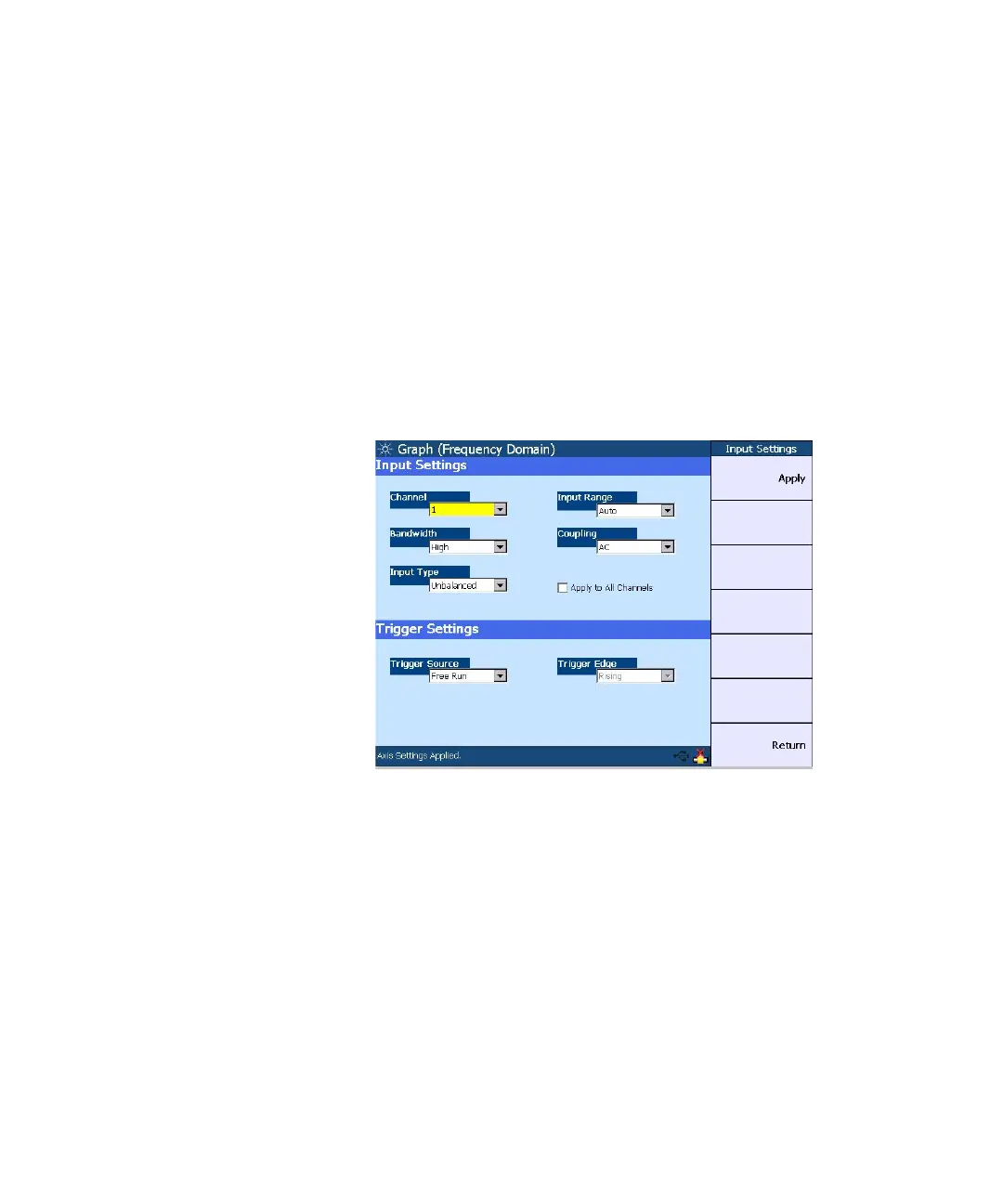
Input settings
The input settings section allows you to select the channel to
be configured, measurement bandwidth, input connection,
input range, and coupling. You may set the trigger source
and trigger edge on the trigger settings section. The trigger
source selection consists of Free Run, External, Channel 1,
and Channel 2.
Refer to Chapter 3, “Input Settings” on page 56 and
“Common Settings” on page 62 for more information on the
input settings.
Figure 6-4 Input settings page
Axis settings
You can manually change the X- axis and Y- axis settings,
such as the minimum and maximum values, as well as select
between linear or log scale. You may perform an Autoscale
to automatically scale the display according to the signal.