EasyManuals Logo

Agilent Technologies u8903a User Manual

Agilent Technologies u8903a
171 pages
To Next Page IconTo Next Page
To Previous Page IconTo Previous Page
Page #82 background imageLoading...
Page #82 background image
60 U8903A User’s Guide
3 Instrument Configuration
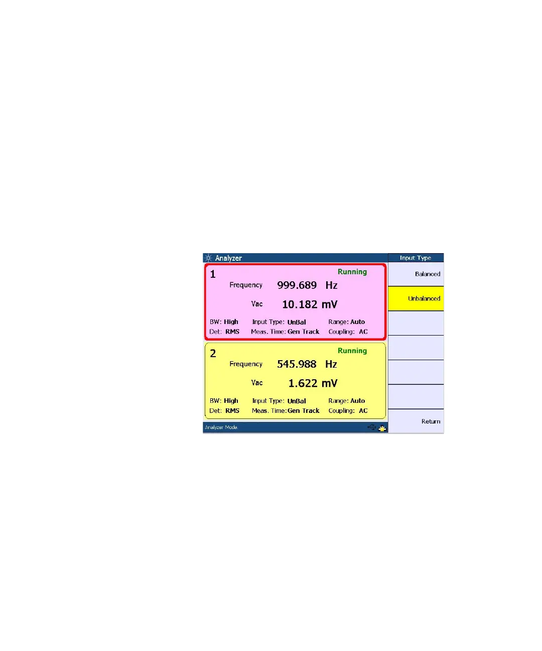
Input configuration
The input signal connectors can be configured as Balanced
or Unbalanced as shown in the following figure. The
Balanced configuration routes signals from the front panel
XLR input connectors to the analyzer. The signals on the
positive and negative XLR pins enter a differential amplifier
where they are subtracted before passing on to the detector.
The Unbalanced configuration selects the front panel BNC
connectors as the input source. The signal in the inner
conductor of the coaxial connector is referenced to ground
for measurement.
Figure 3-6 Input signal connector configuration

Table of Contents

Other manuals for Agilent Technologies u8903a

Questions and Answers:

Question and Answer IconNeed help?

Do you have a question about the Agilent Technologies u8903a and is the answer not in the manual?

Agilent Technologies u8903a Specifications

General IconGeneral
BrandAgilent Technologies
Modelu8903a
CategoryMeasuring Instruments
LanguageEnglish

Related product manuals