54 U8903A User’s Guide
3 Instrument Configuration
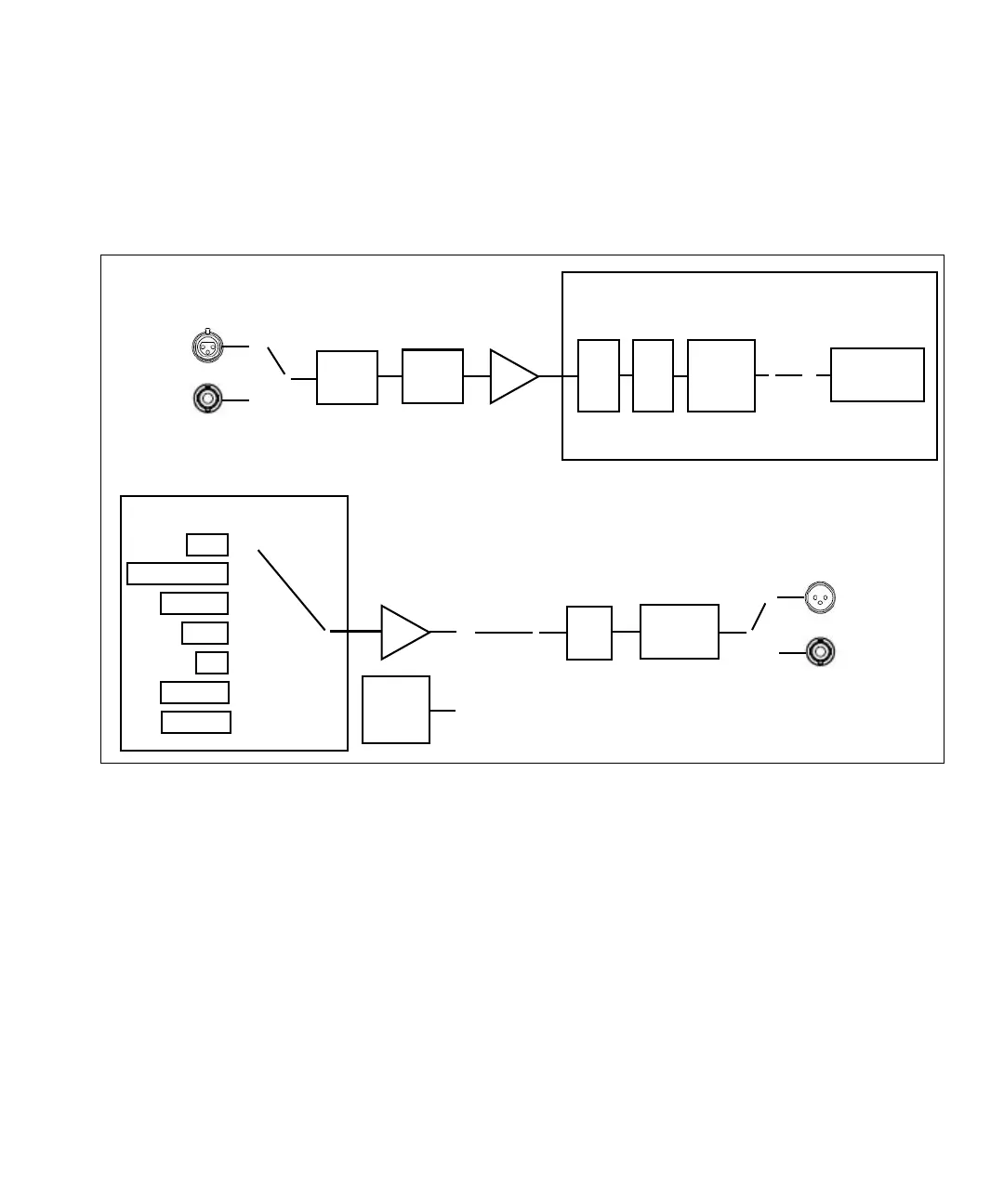
U8903A Block Diagram
A simplified U8903A block diagram is shown as follows.
Figure 3-1 U8903A block diagram
The description for the U8903A block diagram is provided as
follows.
Measurement
An audio signal can enter the analyzer through either the
Balanced (XLR) or Unbalanced (BNC) input signal connector.
The audio signal then passes through the AC/DC coupling
circuit. If AC coupling is selected, its DC component is
blocked, thus only the AC component of the signal passes
through to the Ranging circuit. However, if DC coupling is
selected, the entire signal passes through to the Ranging
circuit.
Inputs
Balanced
Unbalanced
o
o
o
AC/DC
coupling
Ranging
ADC
Low
Pass
filter
Weighting
filter
o
High
Pass
filter
o
Measurement
algorithm
DSP software algorithm
Sine
Variable Phase
Dual Sine
o
o
o
o
DAC
o
o
Gain
Attenuator
o
o
o
Outputs
Balanced
Unbalanced
Square
wave
generator
o
DSP software algorithm
Noise
o
DC
o
Multitone
o
Arbitrary
o