Rockwell Automation Publication 2097-UM001D-EN-P - November 2012 43
Kinetix 300 Drive Connector Data and Feature Descriptions Chapter 3
Figure 17 - Indexing Timing Diagram
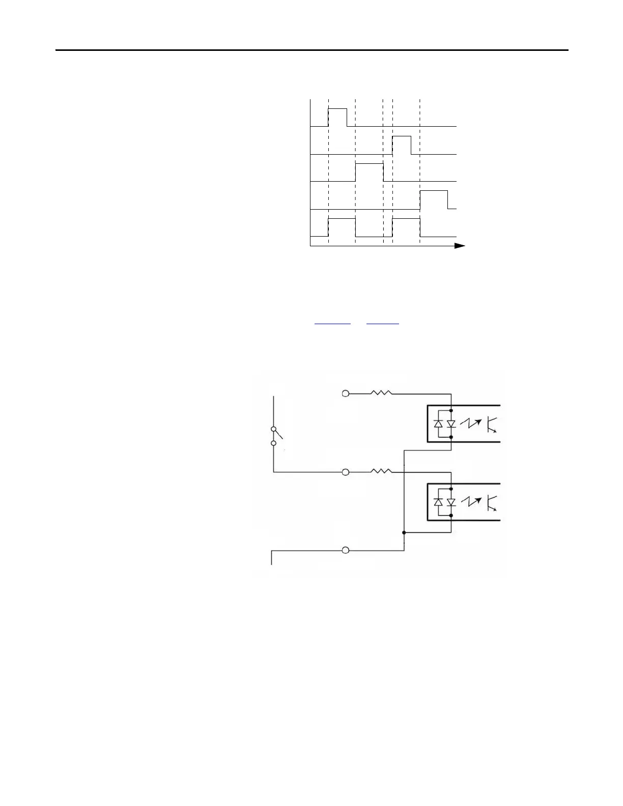
The digital inputs are optically isolated and sinks up to 24V DC. Electrical
details are shown in Ta ble 1 0
on page 44. You can set up the inputs for PNP
sourcing or NPN sinking.
Figure 18 - Sourcing of Digital Inputs
Start Index Input
(digital I/O from MotionView software)
Start Motion Bit in Output Assembly
Abort Index Input
(digital I/O from MotionView software)
Abort Index
(from Output Image)
Drive Status Indexing
The drive must be enabled for homing and indexing mode.
GND
IN_A2
IN_A_COM
+24V
IN_A1
1.2 k
Ω
1.2 kΩ

 Loading...


