24
6
5
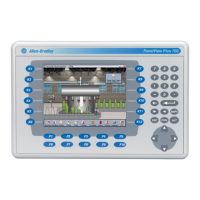
9.0-in. Touch - 8 Levers
3
1
4.3-in. Touch - 4 Levers
5.7-in. Touch - 6 Levers
5
24
8
6.5-in. Touch - 6 Levers
7
6
3
1
2
3
4
3
1
2
4
6
5
1
10
3
29 4
7
5
6
8
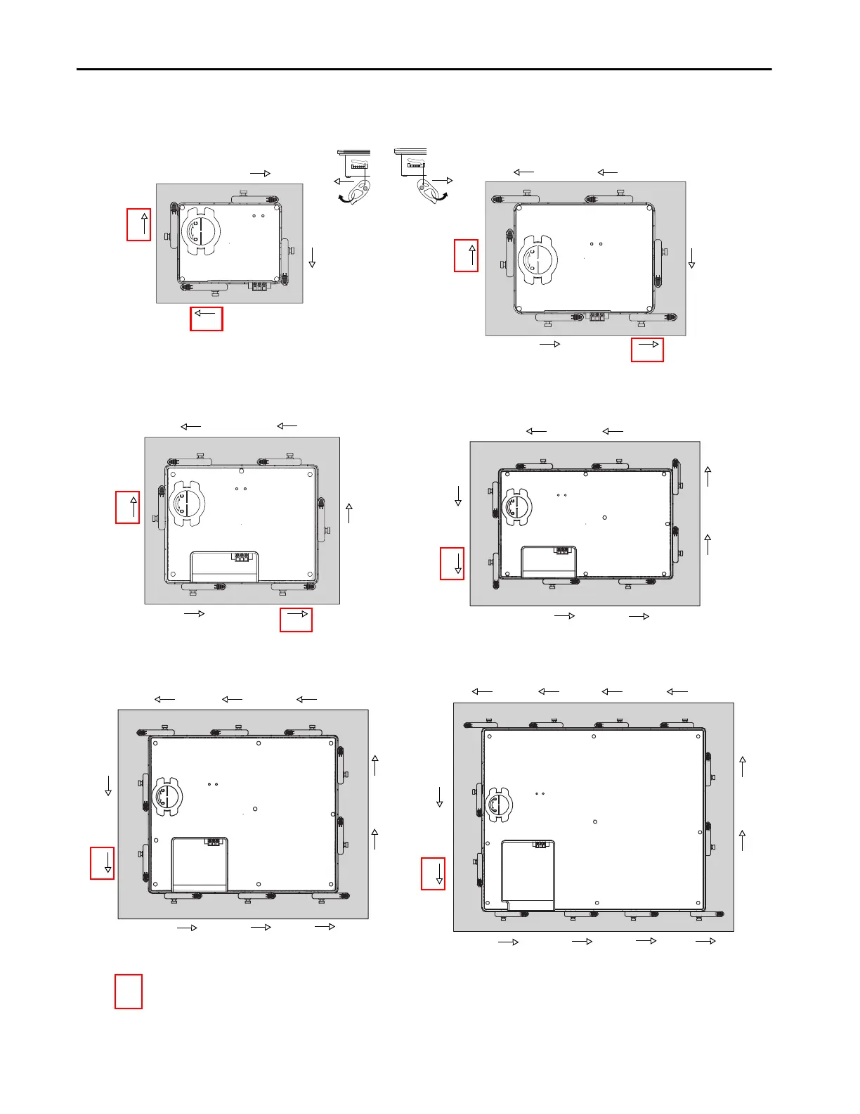
10.4-in. and 12.1-in. Touch - 10 Levers
The box indicates that the levers must be rotated in the
orientation that is shown to avoid interference with
ports and cables.
1
IMPORTANT: The mounting lever orientations that are shown are required to maintain
NEMA, UL Type, and IP seals. If you require a NEMA, UL Type, or IP seal, do not use a
mounting lever in another orientation than shown.
15-in. Touch - 12 Levers
11
9
10
12
7
3
5
1
268
4

 Loading...