Rockwell Automation Publication 1783-UM007G-EN-P - February 2017 103
Install Stratix 5410 Switches Chapter 4
Follow these steps to install the switch.
1. (Optional) Install or remove the SD card.
2. Verify switch operation.
3. Mount the switch on a rack.
or
Mount the switch on a wall.
4. Ground the switch.
5. (Optional) Install a second power supply module in the switch.
6. Wire the power source.
7. (Optional) Install an SFP module.
8. Wire external alarms and attach the alarm relay connector to the switch.
9. Connect to switch ports:
• Ethernet, PoE/PoE+ ports
• SFP/SFP+ ports
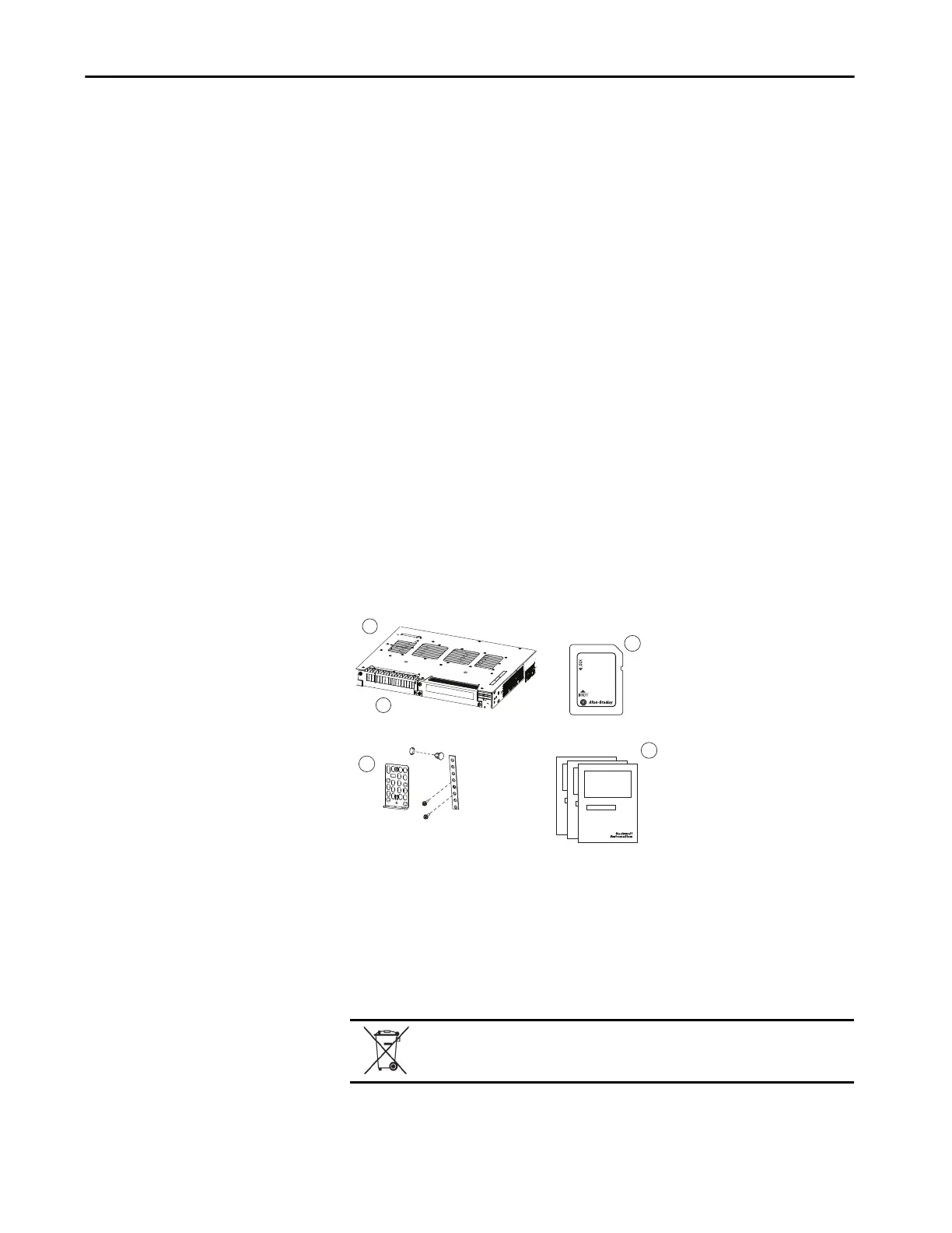
Parts List and Required Tools
Verify that you have these items. The Secure Digital (SD) card and power
supply comes pre-installed in the switch.
1 Stratix® 5410 switch
2 Power supply module
3 SD card
4 Mounting kit
(1)
(1) Replacement kits can be ordered by requesting part number 53-100573-01.
5 Documentation
At the end of its life, this equipment should be collected separately from any
unsorted municipal waste.
1
5
2
PSU OK
PWR-RGD-AC-DC
3
4
 Loading...


