EasyManuals Logo

Allen-Bradley Stratix 5700 User Manual

Allen-Bradley Stratix 5700
548 pages
To Next Page IconTo Next Page
To Previous Page IconTo Previous Page
Page #111 background imageLoading...
Page #111 background image
Rockwell Automation Publication 1783-UM007G-EN-P - February 2017 111
Install Stratix 5410 Switches Chapter 4
Mount the Switch on a Wall
To mount the switch on a wall, see the following:
Attach the Brackets on page 111
Mount the Switch on page 113
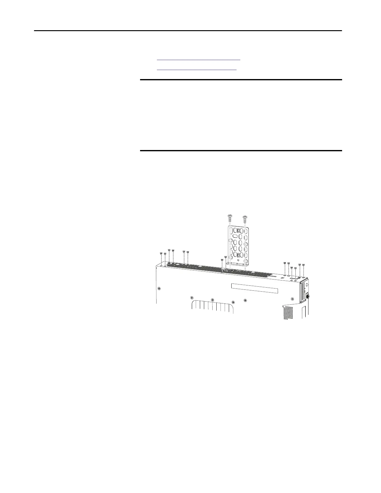
Attach the Brackets
To attach brackets to the switch, follow this procedure.
1. Attach the brackets on both sides of the switch.
IMPORTANT To mount the switch on a wall in an enclosure, follow these minimum
clearances:
Sides of switch facing up and facing down: 9.52 cm (3.75 in.)
Port side: 7.62 cm (3.0 in.)
Power supply side: 13.33 cm (5.25 in.)
Cover side not facing wall: 4.44 cm (1.75 in.)
Base side facing wall: 0 cm (0 in.)
32579-M

Table of Contents

Other manuals for Allen-Bradley Stratix 5700

Questions and Answers:

Question and Answer IconNeed help?

Do you have a question about the Allen-Bradley Stratix 5700 and is the answer not in the manual?

Allen-Bradley Stratix 5700 Specifications

General IconGeneral
ModelStratix 5700
Port TypesRJ45, SFP
MountingDIN Rail or Panel Mount
DimensionsVaries by model
WeightVaries by model
ManagementWeb-based, SNMP, Command Line
RedundancyDevice Level Ring, STP, RSTP
Operating Temperature-40°C to 70°C
Power SupplyDual DC inputs
Input Voltage24 VDC or 100-240 VAC
ProtocolsEtherNet/IP, DLR
Security FeaturesSSH, HTTPS, RADIUS, TACACS+

Related product manuals