EasyManuals Logo

Allen-Bradley Stratix 5700 User Manual

Allen-Bradley Stratix 5700
548 pages
To Next Page IconTo Next Page
To Previous Page IconTo Previous Page
Page #141 background imageLoading...
Page #141 background image
Rockwell Automation Publication 1783-UM007G-EN-P - February 2017 141
Install Stratix 5700 Switches Chapter 5
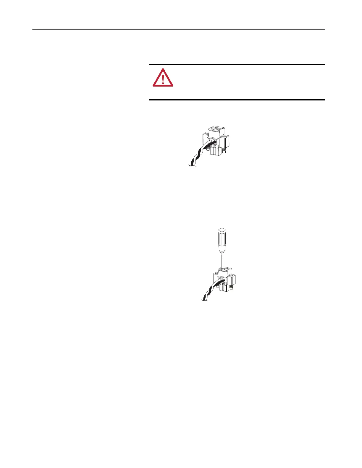
Be sure that you cannot see any wire lead. Only wire with insulation can
extend from the connector.
7. Use a ratcheting-torque screwdriver to torque the captive screws of the
power connector to 0.23 N•m (2.0 lb•in).
Do not exceed the recommended torque.
ATTENTION: An exposed wire lead from a DC input power source can
conduct harmful levels of electricity. Be sure that no exposed portion
of the DC input power source wire extends from the connectors or
terminal blocks.
32279-M
32281-M

Table of Contents

Other manuals for Allen-Bradley Stratix 5700

Questions and Answers:

Question and Answer IconNeed help?

Do you have a question about the Allen-Bradley Stratix 5700 and is the answer not in the manual?

Allen-Bradley Stratix 5700 Specifications

General IconGeneral
ModelStratix 5700
Port TypesRJ45, SFP
MountingDIN Rail or Panel Mount
DimensionsVaries by model
WeightVaries by model
ManagementWeb-based, SNMP, Command Line
RedundancyDevice Level Ring, STP, RSTP
Operating Temperature-40°C to 70°C
Power SupplyDual DC inputs
Input Voltage24 VDC or 100-240 VAC
ProtocolsEtherNet/IP, DLR
Security FeaturesSSH, HTTPS, RADIUS, TACACS+

Related product manuals