Rockwell Automation Publication 1783-UM007G-EN-P - February 2017 151
Install Stratix 5700 Switches Chapter 5
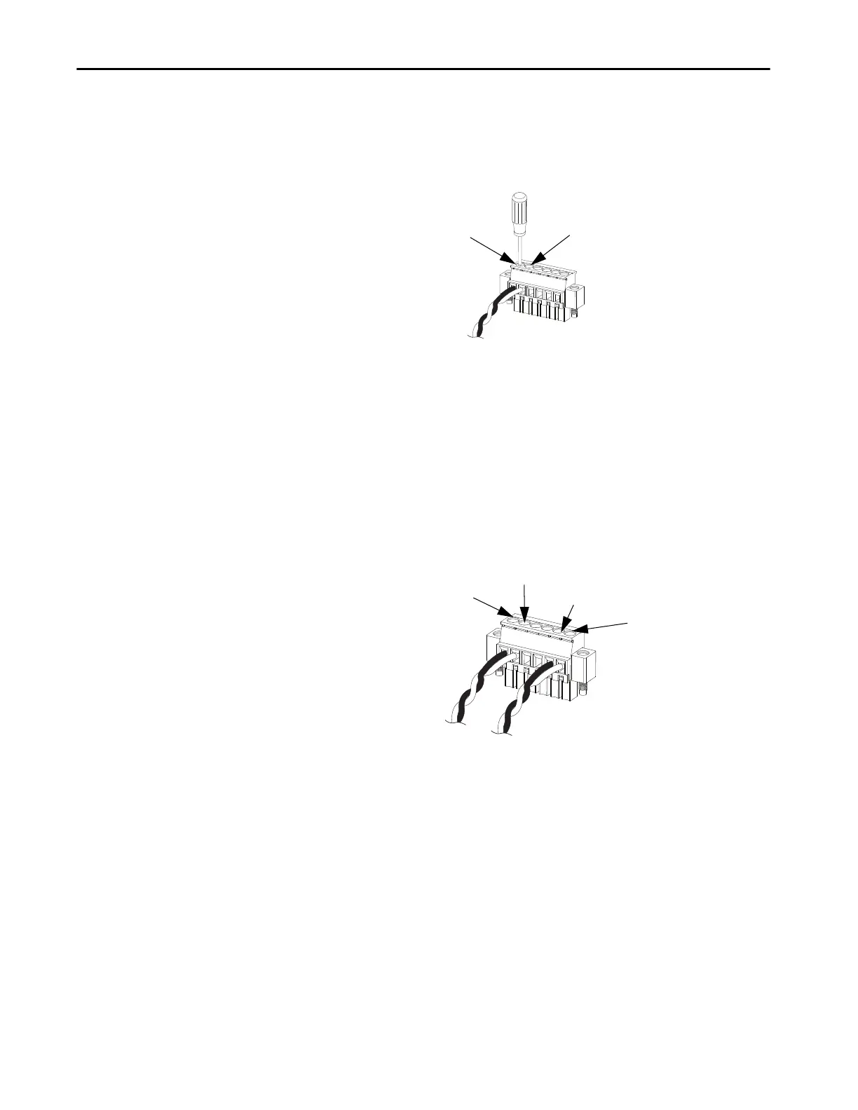
5. Use a ratcheting torque flathead screwdriver to torque the captive screw
of the alarm relay connector to 0.23 N•m (2.0 lb•in).
Do not exceed the recommended torque.
6. Repeat the preceding procedure to insert the input and output wires of
one more external alarm device into the alarm relay connector.
The following figure shows the completed wiring for two external alarm
devices. The first alarm device circuit is wired as an alarm relay input
circuit—the IN1 and REF connections complete the circuit. The
second alarm device circuit is wired as an alarm relay output circuit by
using the normally open side of the form C relay contacts. The NO and
COM connections complete the circuit.
32288-M
IN1 - External Device Connection 1
REF - External Device Connection 2
IN1—External Device Connection 1
REF—External Device Connection 2
COM—Wired Connection
NO—Wired Connection
32289-M

 Loading...


