EasyManuals Logo

Allen-Bradley Stratix 5700 User Manual

Allen-Bradley Stratix 5700
548 pages
To Next Page IconTo Next Page
To Previous Page IconTo Previous Page
Page #165 background imageLoading...
Page #165 background image
Rockwell Automation Publication 1783-UM007G-EN-P - February 2017 165
Install Stratix 8000 and 8300 Switches Chapter 6
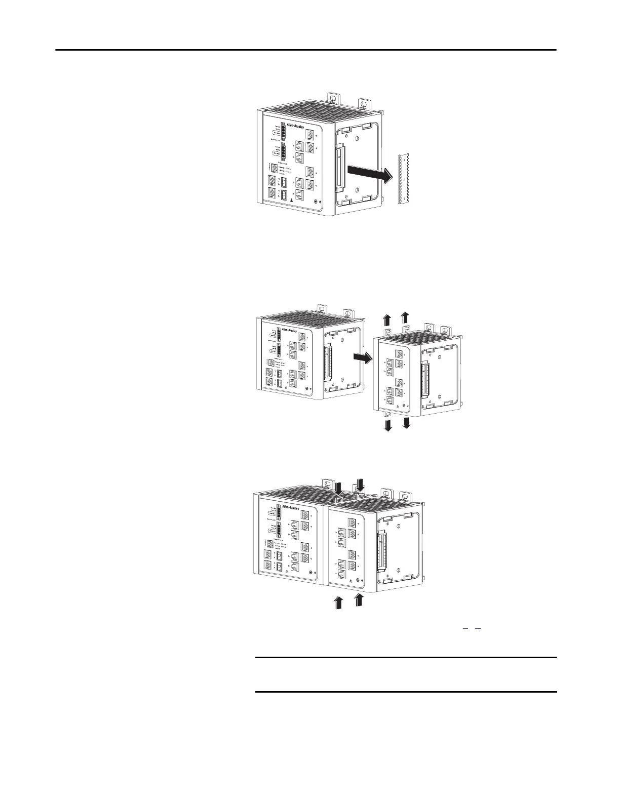
2. Remove the protective EMI-connector cover from the side panel.
3. Push the upper module latches up and the lower module latches down.
Then slide the switch and module together.
The expansion module is shown with the side panel removed. Do not
remove this panel unless you plan to install another module.
4. Push the upper and lower module latches in to secure the module to the
switch.
5. If you are installing a second module, repeat steps
1...4, but secure the
second module to the right side of the first module.
IMPORTANT You cannot install an expansion module to the right of the
1783-MX08F or 1783-MX08S fiber expansion module.
31787-M
31780-M
31781-M

Table of Contents

Other manuals for Allen-Bradley Stratix 5700

Questions and Answers:

Question and Answer IconNeed help?

Do you have a question about the Allen-Bradley Stratix 5700 and is the answer not in the manual?

Allen-Bradley Stratix 5700 Specifications

General IconGeneral
ModelStratix 5700
Port TypesRJ45, SFP
MountingDIN Rail or Panel Mount
DimensionsVaries by model
WeightVaries by model
ManagementWeb-based, SNMP, Command Line
RedundancyDevice Level Ring, STP, RSTP
Operating Temperature-40°C to 70°C
Power SupplyDual DC inputs
Input Voltage24 VDC or 100-240 VAC
ProtocolsEtherNet/IP, DLR
Security FeaturesSSH, HTTPS, RADIUS, TACACS+

Related product manuals