Rockwell Automation Publication 1783-UM007G-EN-P - February 2017 177
Install Stratix 8000 and 8300 Switches Chapter 6
Follow these steps to connect the DC power source and relay connector to the
switch.
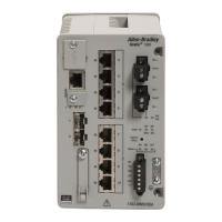
1. Insert the power and relay connector into the Pwr A receptacle on the
switch front panel.
2. Use a screwdriver to tighten the captive screws on the sides of the power
and relay connector.
3. If a second power source is required, insert a second power and relay
connector into the Pwr B receptacle on the switch front panel.
.
4. Use a screwdriver to tighten the captive screws on the sides of the second
power and relay connector.
ATTENTION: If multiple power sources are used, do not exceed the
specified isolation voltage
VRTA A
31786-M
VRTA A
31788-M
VRTA A
 Loading...
