5–12 Chapter 5: IP Core Interfaces
Avalon-ST TX Interface
Cyclone V Hard IP for PCI Express November 2011 Altera Corporation
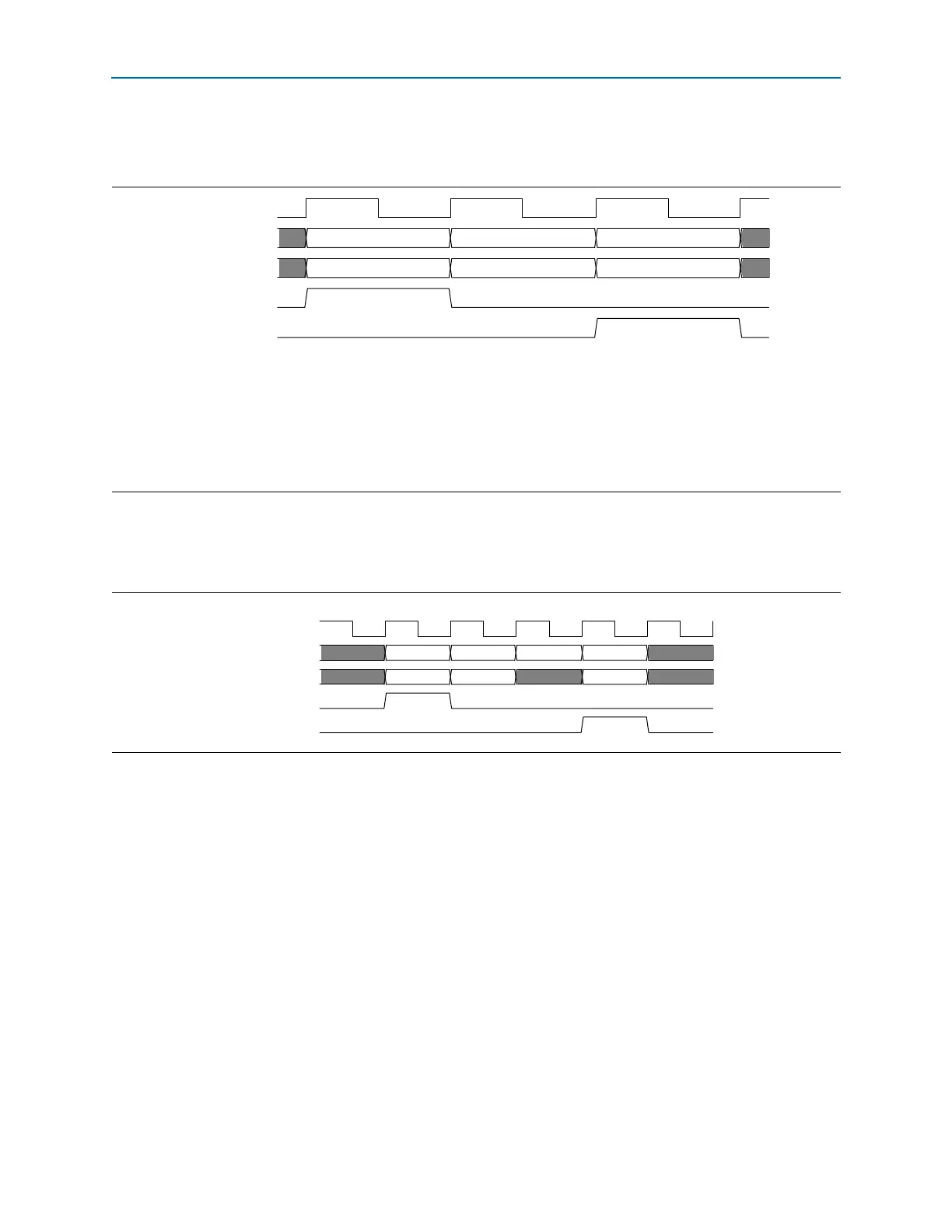
Figure 5–10 illustrates the mapping between Avalon-ST TX packets and PCI Express
TLPs for a four dword header with qword aligned addresses with a 64-bit bus.
Figure 5–11 illustrates the mapping between Avalon-ST TX packets and PCI Express
TLPs for four dword header with non-qword aligned addresses with a 64-bit bus.
Figure 5–10. 64-Bit Avalon-ST tx_st_data Cycle Definition for 4-Dword TLP with Qword Aligned Address
Notes to Figure 5–10:
(1) Header0 = {pcie_hdr_byte0, pcie_hdr _byte1, pcie_hdr _byte2, pcie_hdr _byte3}
(2) Header1 = {pcie_hdr _byte4, pcie_hdr _byte5, pcie_hdr byte6, pcie_hdr _byte7}
(3) Header2 = {pcie_hdr _byte8, pcie_hdr _byte9, pcie_hdr _byte10, pcie_hdr _byte11}
(4) Header3 = pcie_hdr _byte12, pcie_hdr _byte13, header_byte14, pcie_hdr _byte15}, 4 dword header only
(5) Data0 = {pcie_data_byte3, pcie_data_byte2, pcie_data_byte1, pcie_data_byte0}
(6) Data1 = {pcie_data_byte7, pcie_data_byte6, pcie_data_byte5, pcie_data_byte4}
coreclkout
tx_st_data[63:32]
tx_st_data[31:0]
tx_st_sop
tx_st_eop
Header1 Header3 Data1
Header0 Header2 Data0
Figure 5–11. 64-Bit Avalon-ST tx_st_data Cycle Definition for TLP 4-Dword Header with Non-Qword Aligned Address
coreclkout
tx_st_data[63:32]
tx_st_data[31:0]
tx_st_sop
tx_st_eop
Header 1 Header3 Data0 Data2
Header 0 Header2 Data1