4. Configuration
168
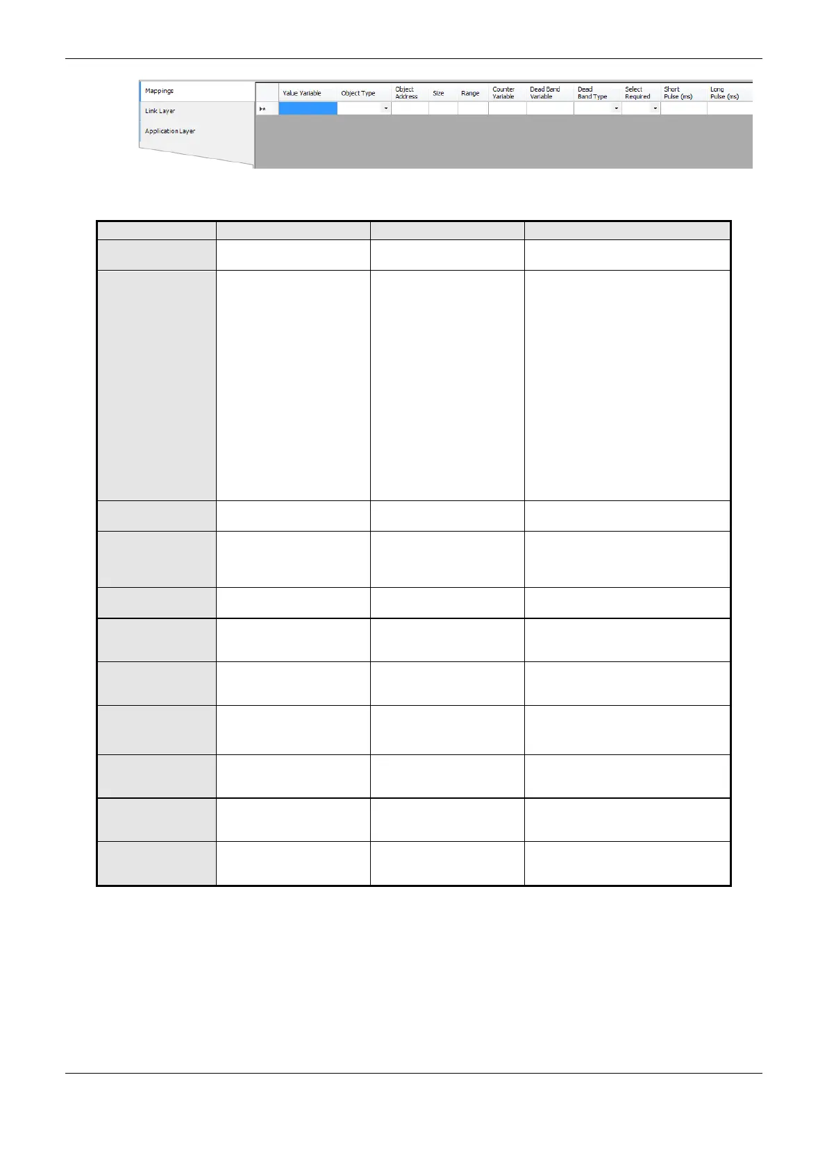
Figure 4-77. Server IEC 60870-5-104 General Parameters Screen
Name of a variable declared in a POU
or GVL
IEC 60870-5-104 object
type configuration
Single Point Information
Double Point Information
Step Position Information
Measured Value (Normalized)
Measured Value (Scaled)
Measured Value (Short Floating
Point)
Integrated Totals
Single Command
Double Command
Regulating Step Command
Setting Point Command (Normalized)
Setting Point Command (Scaled)
Setting Point Command (Short
Floating Point)
IEC 60870-5-104 mapping
first point’s index
Specifies the maximum
data quantity that an IEC
60870-5-104 mapping will
can access
Configured data address
range
Name of the symbolic
variable which will hold the
counter variable’s value
Name of a variable declared in a
POU, GVL or counter module
Name of the symbolic
variable which will hold the
dead band’s value
Name of a variable declared in a POU
or GVL
Defines the dead band type
to be used in the mapping
Absolute
Disabled
Integrated
Defines if it is required a
previous select to run a
command
Defines the short pulse
time to a IEC 60870-5-104
digital command
Defines the long pulse time
to a IEC 60870-5-104
digital command
Table 4-103. Server IEC 60870-5-104 General Parameters Cofiguration
Notes:
Value Variable: When a read command is sent, the return received in the answer is stored in this
variable. When it is a write command, the written value is going to be stored in that variable. He
variable can be simple, array, array element or can be at structures.
Counter Variable: This field applys only on mapping of Integrated Totals type objects, being this
the controller variable to be managed on process. It must has same type and size of the variable
 Loading...