3. Installation
26
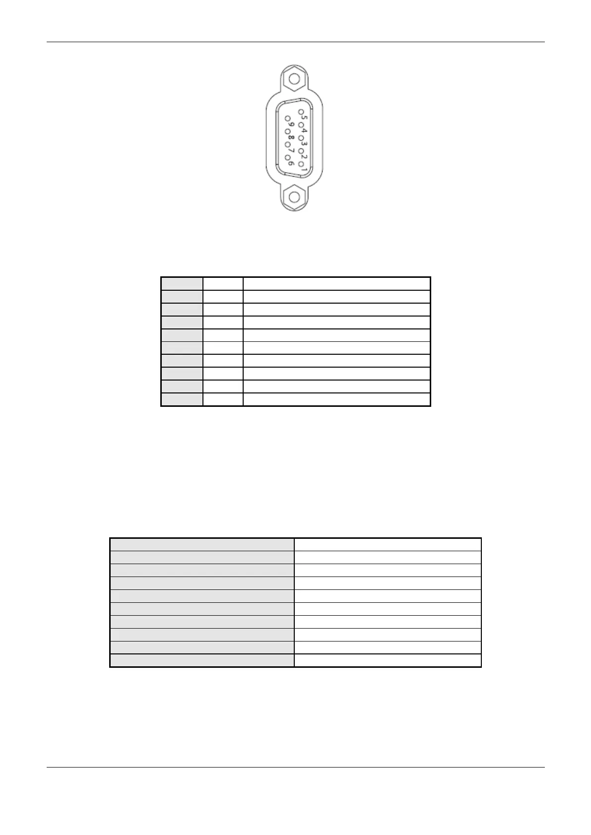
Figure 3-5. DB9 Female Connector, NX3004/NX3005 CPU (COM 1) and NX3010/NX3020/NX3030 CPU
(COM 2)
Internal Termination, positive
Data Transmission, positive
Negative Reference for External Termination
Positive Reference for External Termination
Internal Termination, negative
Data Transmission, negative
Table 3-5. DB9 Female Connector Pin Layout, COM 1 (NX3004/NX3005) and COM 2
(NX3010/NX3020/NX3030)
RS-485 Communication without termination
In order to connect in a RS-485 network with no termination in COM 1 (NX3004 or NX3005) or
COM 2 (NX3010, NX3020 or NX3030) interface, the cable AL-1763 identified terminals must be
connected in the respective device terminals, as shown on Table 3-6.
Table 3-6. RS-485 Connections with no Termination
The Figure 3-6 diagram indicates how the AL-1763 connection terminals should be connected in the
device terminals.
 Loading...