3. Installation
24
Five ARP commands are triggered within a 200 ms initial interval, doubling the interval every new
triggered command, totalizing 3 s. Example: first trigger occurs at time 0, the second one at 200 ms
and the third one at 600 ms and so on until the fifth trigger at time 3 s.
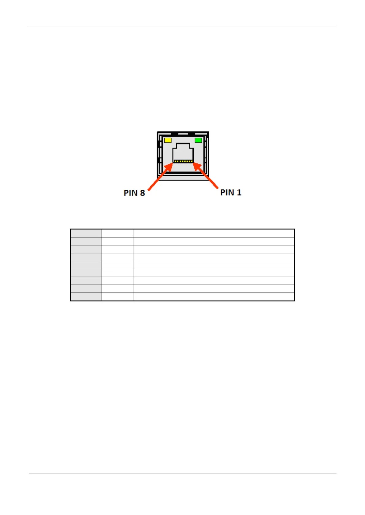
Network Cable Installation
Nexto Series CPUs Ethernet ports, identified on the panel by NET 1 and NET 2 (NX3020 and
NX3030), have pattern pin outs which are the same used in PCs. The connector type, cable type,
physical level, among other details regarding the CPU and the Ethernet network device are defined in
the Technical Description –Ethernet Interfaces Configuration Figure 3-3 and Table 3-3 present the
RJ-45 Nexto CPU female connector, with the identification and description of the valid pin out for
10Base-T and 100Base-TX physical levels.
Figure 3-3. RJ45 Nexto CPU Female Connector
Data transmission, positive
Data transmission, negative
Table 3-3. RJ45 Nexto CPU Female Connector Pin out
The interface can be connected in a communication network through a hub or switch, or straight from
the communication equipment. In this last case, due to Nexto CPUs Auto Crossover feature, there is
no need for a cross-over network cable, the one used to connect two PCs point to point via Ethernet
port.
It is important to stress that it is understood by network cable a pair of RJ45 male connectors
connected by a UTP or ScTP cable, category 5 whether straight connecting or cross-over. It is used to
communicate two devices through the Ethernet port.
These cables normally have a connection lock which guarantees a perfect connection between the
interface female connector and the cable male connector. At the installation moment, the male
connector must be inserted in the module female connector until a click is heard, assuring the lock
action. To disconnect the cable from the module, the lock lever must be used to unlock one from the
other.
 Loading...