6. Redundancy with NX3030 CPU
265
Technical Description and Configuration
Minimum Configuration of a Redundant CPU (Not Using PX2612 Panel)
A redundant CPU is composed, at least, by:
Two identical half-clusters
Each half-cluster consists of at least the following modules:
The rack itself where the modules are inserted, which can be one of the following:
o NX9000, with 8 positions
o NX9001, with 12 positions
o NX9002, with 16 positions
o NX9003, with 24 positions
The power supply NX8000, at rack positions 0 and 1;
The NX3030 CPU, at rack positions 2 and 3;
The module NX4010, at rack positions 4 and 5.
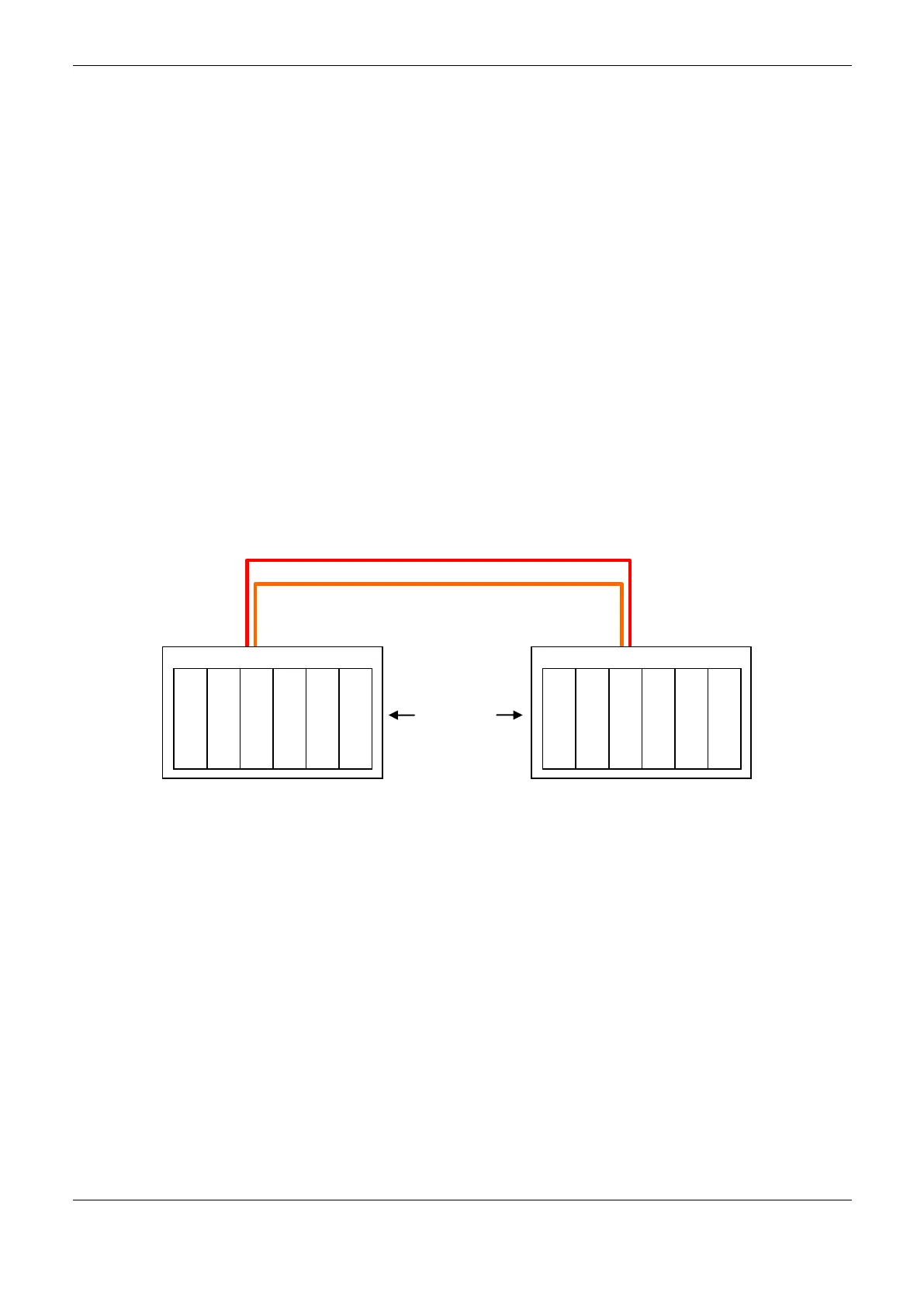
Figure 6-2 shows an example of a redundant CPU minimum configuration, using the smallest rack
(NX9001, with 12 positions). In this case, it can be observer that the three modules inserted in the
rack have double width (occupy two rack positions).
Figure 6-2. Minimum configuration of a redundant CPU in rack NX9001
Typical Configurations of a Redundant CPU
A minimum configuration, as the one shown on Figure 6-2, may already work as “redundant
processing unit”. It would be possible to use the serial and Ethernet communication channels from
NX3030 CPU, for instance, for MODBUS TCP communication with a SCADA system, and
MODBUS RTU and/or MODBUS TCP communication with smart field devices or MODBUS
remote I/O systems.
In typical configurations, however, additional modules are inserted in the PLCA and PLCB half-
clusters, for instance, to deliver a remote PROFIBUS I/O and Ethernet additional channels.
Among the additional modules which, optionally, may be inserted in the half-clusters, are the
following:
PROFIBUS Masters NX5001
0 1 2 3 4 5 6 7 8 9 10 11
Synchonism channel NETA (AL-2319)
Synchonism channel NETB (AL-2319)
0 1 2 3 4 5 6 7 8 9 10 11
 Loading...