3. Installation
28
Diagram Note:
The not connected terminals must be insulated so they do not make contact with each other.
RS-485 Communication with External Termination
In order to connect to a RS-485 network using a COM 1 (NX3004 or NX3005) or COM 2 (NX3010,
NX3020 or NX3030) interface external termination, the AL-1763 cable identified terminals must be
connected in the respective device terminals according to the Table 3-8.
Table 3-8.RS-485 Connections with External Termination
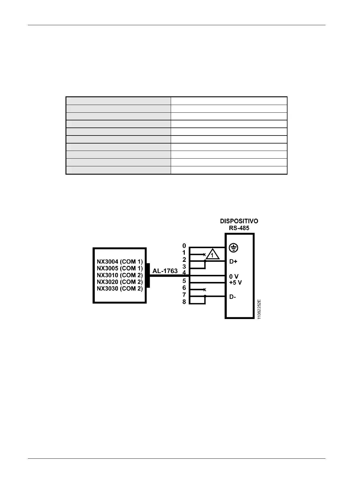
The Figure 3-8 diagram indicates how the AL-1763 connection terminals should be connected in the
device terminals.
Figure 3-8. COM 2 with RS-485 Connections Diagram with External Termination
Diagram Note:
The not connected terminals must be insulated so they do not make contact with each other.
Example of Connection of a RS-485 Network with External Termination and Master
Redundancy
Figure 3-9 below shows an example of RS-485 network connection with external termination, using
two Nexto NX3030 CPUs with half-cluster redundancy as master.
 Loading...