6. Redundancy with NX3030 CPU
309
Thus, a command run by the user to disable an interface will not run the way it’s expected. For
example, if an interface has the status of this bit changed from TRUE to FALSE on an active CPU,
this will not be interpreted as a failure that would take the CPU Active for the Inactive state. In this
case, the CPU will remain in active and the other CPU that will go to the inoperative state. For these
reasons, this command bit should not be manipulated by the user in a redundant application.
For further information regarding PROFIBUS networks configuration, see PROFIBUS-DP NX5001
Utilization Manual.
PROFIBUS Remotes Configuration
To configure PROFIBUS remotes under a NX5001 master, the PROFIBUS-DP NX5001 Master
Utilization Manual must be consulted, together with the following manuals:
Ponto Series Utilization Manual
PROFIBUS PO5063V1 Head Utilization Manual and Redundant PROFIBUS PO5063V5 Head
PROFIBUS PO5064 Head Utilization Manual and Redundant PROFIBUS PO5065 Head
HART over PROFIBUS Network Utilization Manual
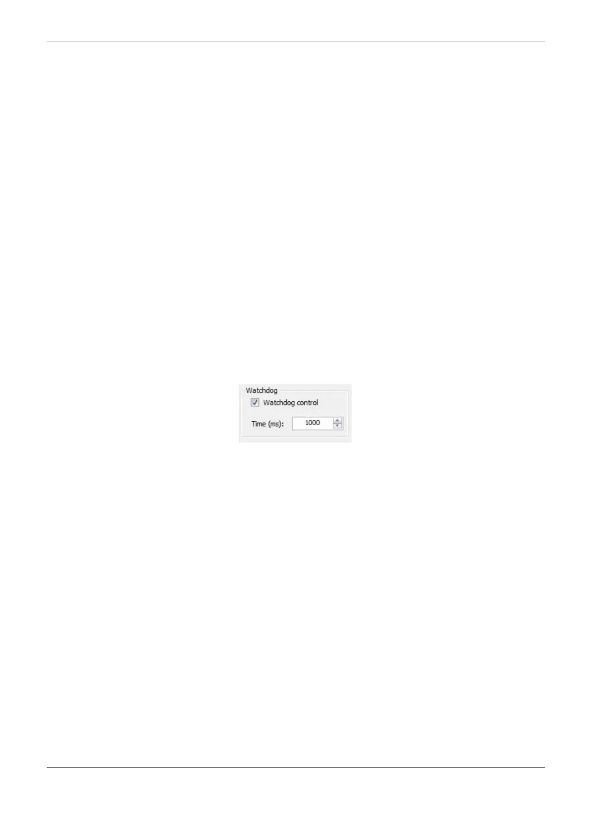
For a redundant system we must pay attention to the configuration of the watchdog parameter from
the PROFIBUS remote. In case that, in the remote configuration screen, the “Watchdog control”
checkbox is checked, the “Time” field needs to be correctly configured. There are two options to
configure the Time and we must use the bigger time between:
WT ≥ I x 2 + 500ms; and
WT ≥ I x 3;
Where WT is the watchdog time and I is the MainTask configured interval.
Figure 6-23. Watchdog Configuration of a PROFIBUS Remote
NX5000 Modules Configuration
NX5000 Modules Insertion or Removal
NX5000 modules can be inserted or removed from the half-cluster rack. To execute this operation
correctly, one must be aware that the number of NX5000 modules in each half-cluster can vary
between zero and six. Care must be taken to the fact that modules which form a redundant NIC
Teaming pair must be inserted in side by side positions in the rack.
In the next project compilation, MasterTool check the possible errors the user may have committed at
inserting or removing NX5000 modules manually. For instance, if the user inserted more than 6
NX5000 modules, an error occurs.
The interface of each module will be identified as NET 1, as they are identified physically on the
product. In case the user adds manually NX5000 modules in the bus, the identification occurs the
same way as the Wizard.
After inserting or removing the NX5000 modules, the configuration of the NX5000 modules
remaining in the rack must be checked.
 Loading...