6. Redundancy with NX3030 CPU
308
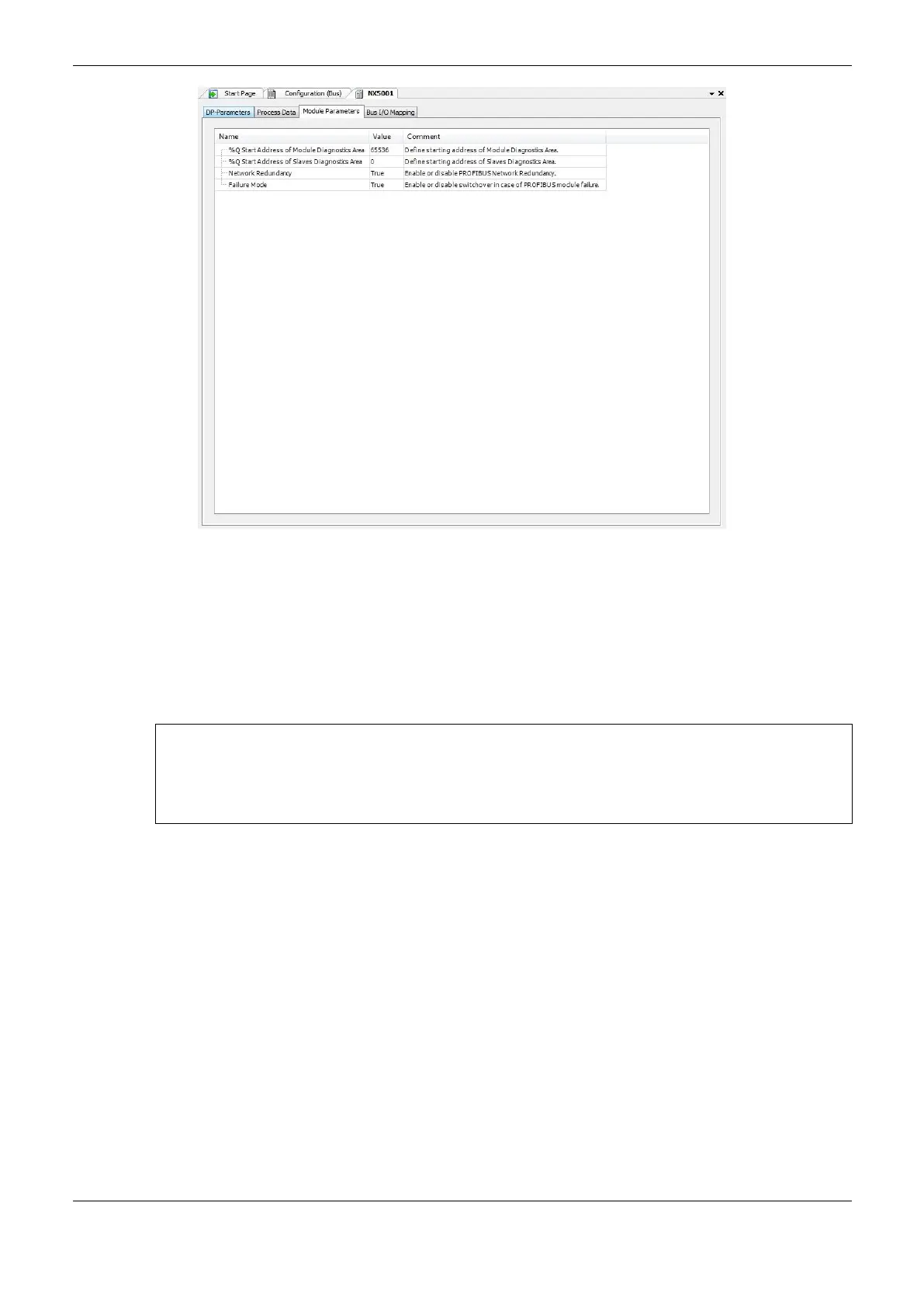
Figure 6-22. NX5001 redundancy parameters
For grouping two NX5001 modules in a redundant PROFIBUS network, a double click must be
executed on an ungrouped NX5001 module which has another ungrouped NX5001 module at its
right in the rack. Next the parameter “Network Redundancy”, available at the tab “Module
Parameters”, must be marked as TRUE, as shown on the Figure 6-22. In order to ungroup it, the same
procedure must be followed, but marking the parameter as FALSE. If this parameter is marked as
TRUE, the DP parameters and the NX5001 parameters at its right are blocked for edition.
ATTENTION:
In case of redundant networks, only the parameters of the NX5001 to the far left on the bus must be
adjusted, while the NX5001 at the right remain blocked for edition. Some network parameters are
identical to the other network while others are calculated automatically from network parameters of
the left NX5001.
It’s recommended for the configured address for a NX5001 master in a redundant PLC to be 2, as the
master NX5001 address in the Non-Active PLC is decremented one unit, thus the NX5001 master
address results 1.
Besides that, it’s important to remember:
The addresses from 3 to 125 are usually used for PROFIBUS slaves
The 0 addresses are frequently used for device configuration and diagnostics
The address 1 is reserved to be taken, dynamically, by the PROFIBUS master in the Non-Active
PLC (PROFIBUS master in passive mode)
The 126 address is frequently used for slave devices when comes from the manufacturer
The 127 address is used for broadcast frames
In the next project compilation, MasterTool check the possible errors the user may have made at
inserting or removing NX5001 modules manually.
Important to note that during the execution of a project previously configured with redundant
NX5001 modules, bit 0 Command (Channel Enable Interface% QXn.0 at Bus tab: I/O Mapping) is
handled by the redundant application. The interfaces must remain qualified throughout the program.
 Loading...