6. Redundancy with NX3030 CPU
267
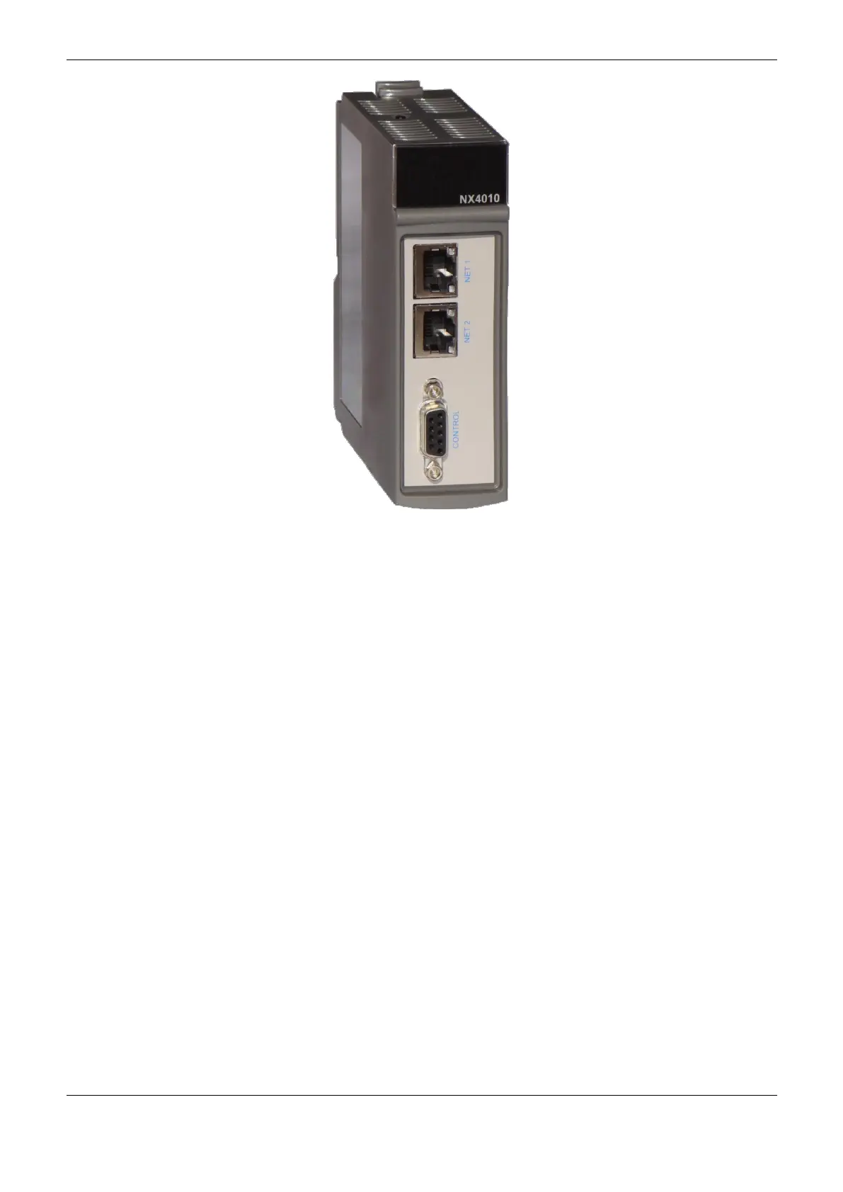
Figure 6-3. NX4010 Module
NX4010 Features
Its main features are:
Data and application synchronization between two half-clusters;
Redundant communication interface between two half-clusters;
Automatic switchover (active half-cluster change) in case of NX4010 and CPU communication
time out;
Possibility to switch off the other half-cluster;
One Touch Diag TM;
Electronic Tag on Display;
Display and LEDs for diagnostics indication
Other features (generals, electrical, mechanic and environment) are presented in the NX4010
Redundancy Module Technical Features - CE114900.
Redundancy Control Panel PX2612
The PX2612 control panel is an optional item in a redundant system. It must be used when the
‘redundancy with panel’ option is selected during the project creation using the wizard. Figure 6-4
shows the redundancy control panel, while Figure 6-5 shows the frontal panel with details.
Through the DB9 connector called CONTROL PLC A, the connection with the CONTROL
connector from PLCA NX4010 is made, using the AL-2317/A cable.
Through the DB9 connector called CONTROL PLC B, the connection with the CONTROL
connector from PLCB NX4010 is made, using the AL-2317/B cable.
Furthermore, there’s a connector with 5 male terminals:
GND: terminal for ground connection;
 Loading...