6. Redundancy with NX3030 CPU
310
NX5000 Modules Configuration
For each NX5000 module in a redundant PLC, the address parameters must be adjusted as described
in the IP Change Methods section, which can be accessed through a double click on the NET 1
interface, below each NX5000 module placed on the devices tree.
ATTENTION:
In case two consecutive modules form a redundant NIC Teaming pair, only the basic parameters of
the left NX5000 should be edited, the right NX5000’s parameters edition will be blocked.
NX5000 Modules Grouping with NIC Teaming Redundancy
The NX5000 modules, as the CPU NX3030 and NX3020 NET 1 interface, present a screen of
advanced configuration which defines if the module forms a redundant NIC Teaming pair with the
module at its right. The configuration is made as described in the NIC Teaming between NET 1 and
NET 2.
To group two NX5000 modules with a redundant pair, the following conditions must be true:
Both NX5000 modules must be inserted in close positions in the rack.
At doing this the right module has its parameters edition blocked and the left module parameters turn
to be the same to both modules.
Unmarking the checkbox “Redundancy of Communication” at the left module causes the modules’
separation, making them behaves as individual modules without NIC Teaming redundancy again.
Failure Vital Setting
The NX5000 modules as well as the NET 1 and NET 2 interfaces allow you to configure if the
interface will generate a switchover in case of failure, as described in Ethernet Interfaces Use with
Vital Fault Indication When configured in conjunction with the NIC Teaming redundancy vital
failure will be considered when failure occurs in both modules of the redundant pair.
NX4010 Redundancy Configuration
The configuration regarding the %I, %Q and %M redundant variables can be accessed through a
double click on the NX4010 module, following the selection of the tab “Redundancy Parameters”.
To understand these parameters the sections Redundant and Non-redundant %I Variables, Redundant
and Non-redundant %I Variables and Redundant and Non-redundant %I Variables must be read.
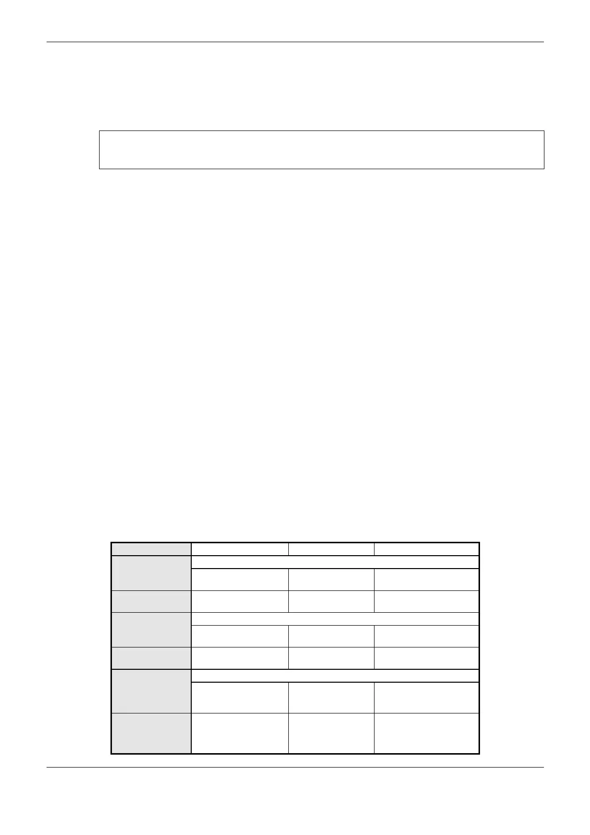
The following parameters must be configured:
Redundancy %M
memory offset
Redundant %M
memory initial address
Redundancy %M
memory length
Redundancy %I
memory offset
Redundant %I memory
initial address
Redundancy %I
memory length
Redundancy %Q
memory offset
reserved for I/O
drivers
%Q redundant memory
offset reserved for I/O
drivers initial address
Redundancy %Q
memory length
reserved for I/O
drivers
%Q redundant memory
offset reserved for I/O
drivers size
 Loading...