CHAPTER 5: MAINTENANCE
LW500A/LW600A PULSED Nd:YAG LASER
990-539 5-21
4. Place a beam expander and IR Power Meter somewhere in the optical beam path after the corner
mirror (as shown above). The purpose of the beam expander is to decrease the energy density
on the face of the IR Detector. If any optical components are removed, it will be necessary to re-
align the Laser after this procedure. Proceed with caution.
5. Turn the Laser ON. Once the SCHEDULE screen appears, turn the High Voltage (HV) OFF.
6. Adjust VR2 (OFFSET) on the ME-1906 PCB for a reading of 0.01 to 0.03 volts on the DMM.
7. Turn the High Voltage (HV) ON and allow the Laser to reach the READY state.
8. Open the Main Shutters.
9. Put the Laser in to
MAINTENANCE mode (see Chapter 3, Section IV. Maintenance Mode Screen
for details).
10. Navigate to the
CONTROL field and change the mode to CURRENT.
11. Select the SCHED button to access the SCHEDULE screen.
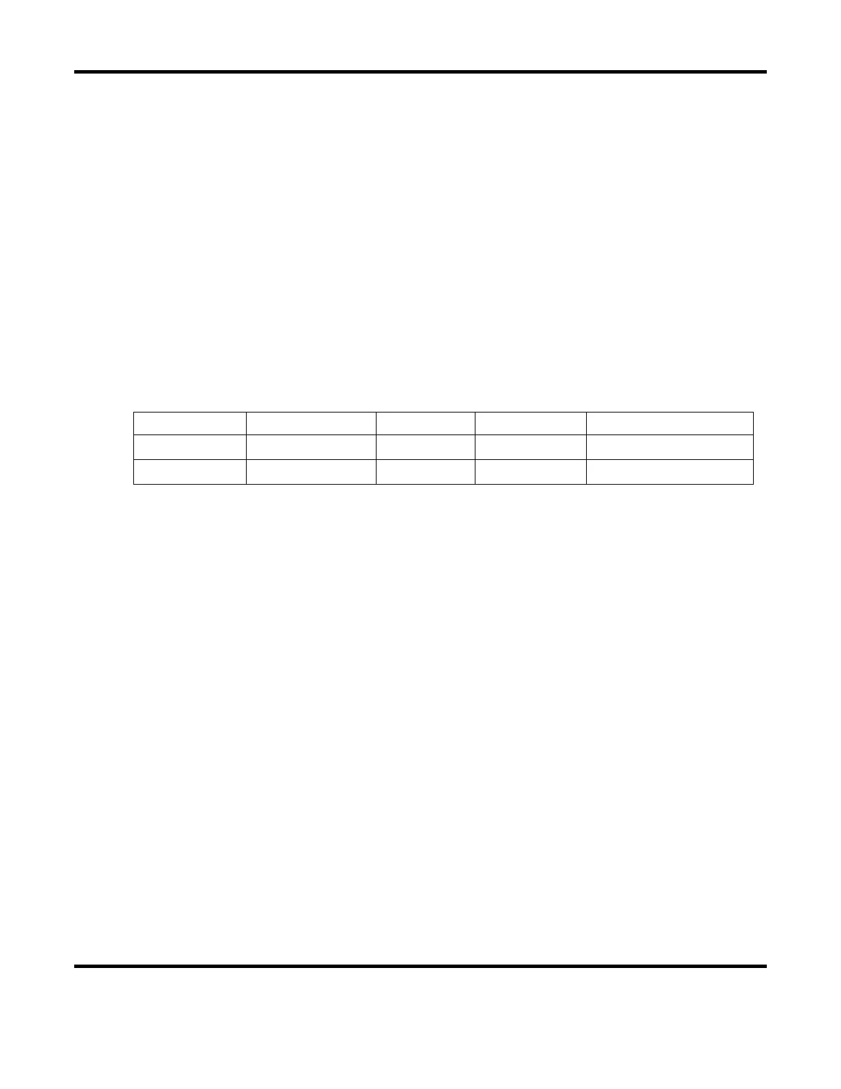
12. Enter the operating parameters according to the table below:
Laser Model Peak Power (A) Power (%) Pulse Width Ideal Output Energy
LW500A 510A 100% 10mS 40J
LW600A 600A 100% 10mS 60J
13. Turn the Guide Beam ON momentarily to verify all light is hitting the center of the IR Power
Detector in a wide pattern (≥ 50% coverage is recommended). If necessary, re-position the beam
expander or IR Power Detector.
14. Fire the Laser and increase or decrease the Peak Power (A) until the Ideal Output Energy (defined
in the table above) is measured by the IR Power Meter.
15. Adjust VR1 on the ME-1906 Power Detector PCB until the measured energy on the Laser LCD
screen equals the measured value on the IR Power Meter.
NOTE: turning VR1 clockwise decreases the LCD energy value, likewise turning VR1 counter-
clockwise increases the LCD energy value).
16. If VR1 is adjusted, repeat steps 6 – 16 until no further adjustments are necessary.
17. Get back into the
MAINTENANCE mode screen and set the CONTROL method back to LASER
POWER
.
18. Remove the Beam Expander and IR Power Detector.
19. Remove the DMM and reinstall the ME-1906 plastic protective cover.
20. If any optical components were removed during this process, re-align the Laser.
21. Re-install the Branch Unit and Head covers back on to the Laser.