Putting to operation
100
Cirrus 3/4/6000 DB2034 08.04
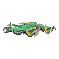
8. Remove all supply line couplings between tractor
and machine.
9. Cover the hydraulic plugs and coupling heads of the
brake and supply line by using dust caps.
10. Affix all supply lines according to their identification
(Fig. 152/1) in the retainer (Fig. 152/2).
Important!
When uncoupling the air pressure
brake lines first remove the red
coupling head (supply line) from the
tractor and then the yellow coupling
head (brake line).
Fig. 152
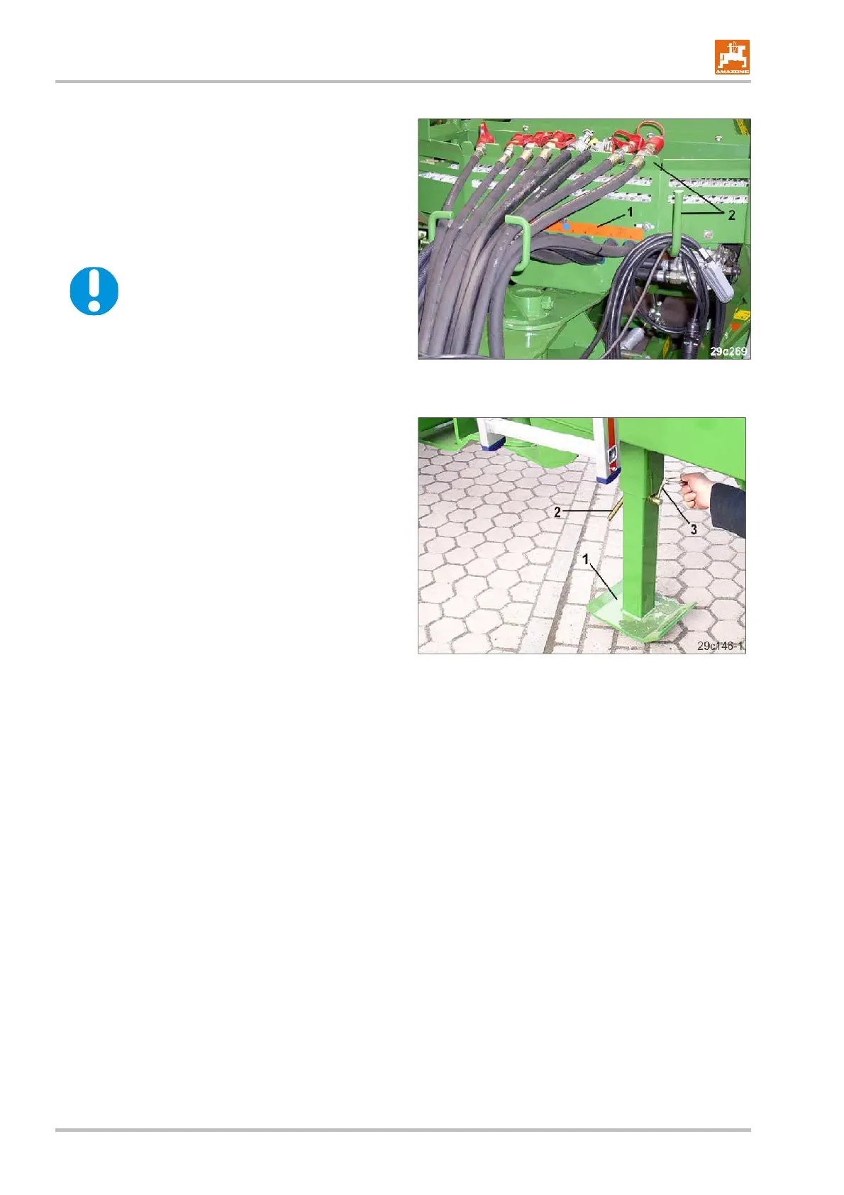
11. Hold the jack (Fig. 153/1) and remove the locking
pin (Fig. 153/2).
12. Lower the jack and secure with the locking pin.
13. Secure the locking pin by using the clip pin (Fig.
153/3).
Fig. 153
 Loading...