Initial operation
Cirrus 3/4/6000 DB2034 08.04
91
6.2 Fitting advice for the connection of the hydraulic blower fan drive
At the pressure side the blower fan motor (Fig. 134/1) can be connected with a single
or a double acting control spool valve (Fig. 134/8) with priority control.
In order to avoid any damage on the blower fan motor, the oil pressure in the return
flow (Fig. 134/6) must not exceed 10 bar.
For this reason never connect the return flow with the control spool valve (Fig. 134/8)
or another control spool valve, but on the pressure free return flow with large plug
coupling (DN 16, Fig. 134/11)!
If it is necessary to install a new return flow tubing, use only tubes DN 16, e.g. Ø20 x
2,0 mm and ensure short return flow ways.
The hydraulic oil must be guided through an oil filter (Fig. 134/7) at any place of
choice.
Ensure that the hydraulic oil never gets too hot. Large oil delivery amounts in
conjunction with small oil tanks promote the quick heating up of the hydraulic oil. The
capacity of the oil tank (Fig. 134/9) should at least have the double of the oil delivery
amount. If the oil heats up too much, the installation of an oil cooler on the tractor by a
professional workshop is necessary.
If it is necessary to drive besides of the blower fan hydrostatic motor yet another
hydrostatic motor, both motors should be switched parallel. When switching both
motors in line, the maximum permissible oil pressure of 10 bar will be always
exceeded behind the first motor.
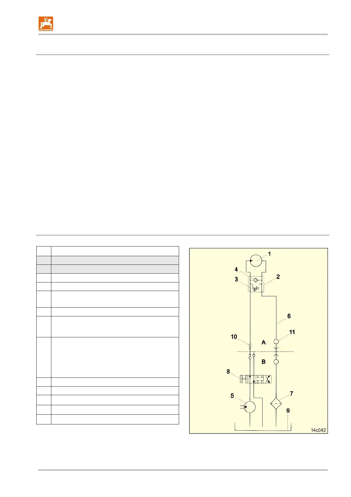
6.2.1 Circuit diagram for hydraulic blower fan drive
No.
Description
A
Implement side
B
Tractor side
1
Blower fan hydrostatic motor N
max.
= 4000 R.P.M.
2
Pressure relief valve with hydraulic free wheel
3
Controllable pressure relief
4
Check valve
5
Tractor hydraulic pump
(the capacity of the tractor hydraulic pump must be in
minimum 80 l/min. at 150 bar)
6
Free return flow
• Inner tube diam. min. Ø16 mm
• Use couplings with sufficiently large inner
diameter
• The return pressure in the return flow tube must
not exceed 10 bar.
7
Filter
8
Single or double acting control valve with priority
9
Hydraulic oil tank
10
Plug coupling
11
Plug coupling "large"
Fig. 134
 Loading...