User manual Assembly, Installation, Start Up
POWER The LED indicates if there is sufficient operating power available for the FX
Controller (10.5 - 13.5 V DC). If this LED is not lit, change the power supply.
4.2.2 Internal sockets
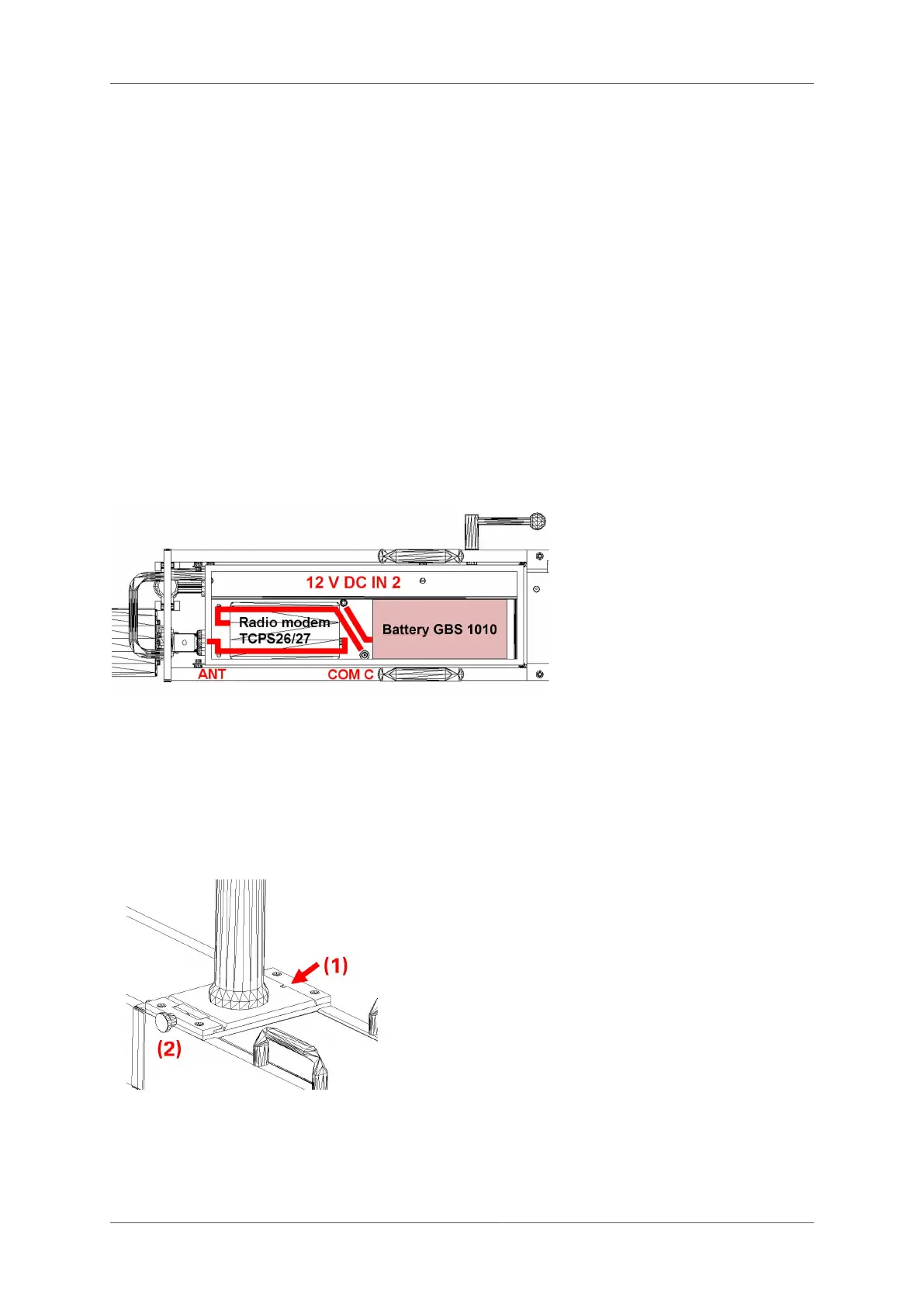
In the compartment of the track trolley TGS FX, the radio modem (optional) and the battery are
installed and connected as shown.
You will also find the following connections:
12V In 2 Attach the battery GBS 1010 to this socket. If an external power source is
connected (12V In 1), the power supply is taken exclusively from the external
source.
COM C Serial interface C connects to a Leica radio modem. Each type of modem requires
a specific cable. Standard factory setting is COM 14.
COM D Serial interface D connects to a Leica radio modem in the GRP TSC of a VMS
1000 configuration. Each type of modem requires a specific cable.
ANT Antenna cable connection with the external antenna for the Leica radio modem.
4.3 Installation of the Prism column GPC 100
Configuration GRP 1000: The prism column GPC 100 is installed on the track trolley TGS FX
as follows:
■
Ensure that the track trolley is securely
fastened together.
■
Line up indentation marked (1) on the
base plate of the prism column with the
protrusion and slide into position.
■
Fully tighten the screw marked (2) and
ensure that the base plate is pushed right
against the back.
4.4 Installation of the Profiler FX
Configuration GRP/IMS 3000: The Profiler FX is installed on the track trolley TGS FX as follows:
© Amberg Technologies AG, 2023 Page 45 of 114