Assembly, Installation, Start Up User manual
■
Ensure that the track trolley is securely
fastened together.
■
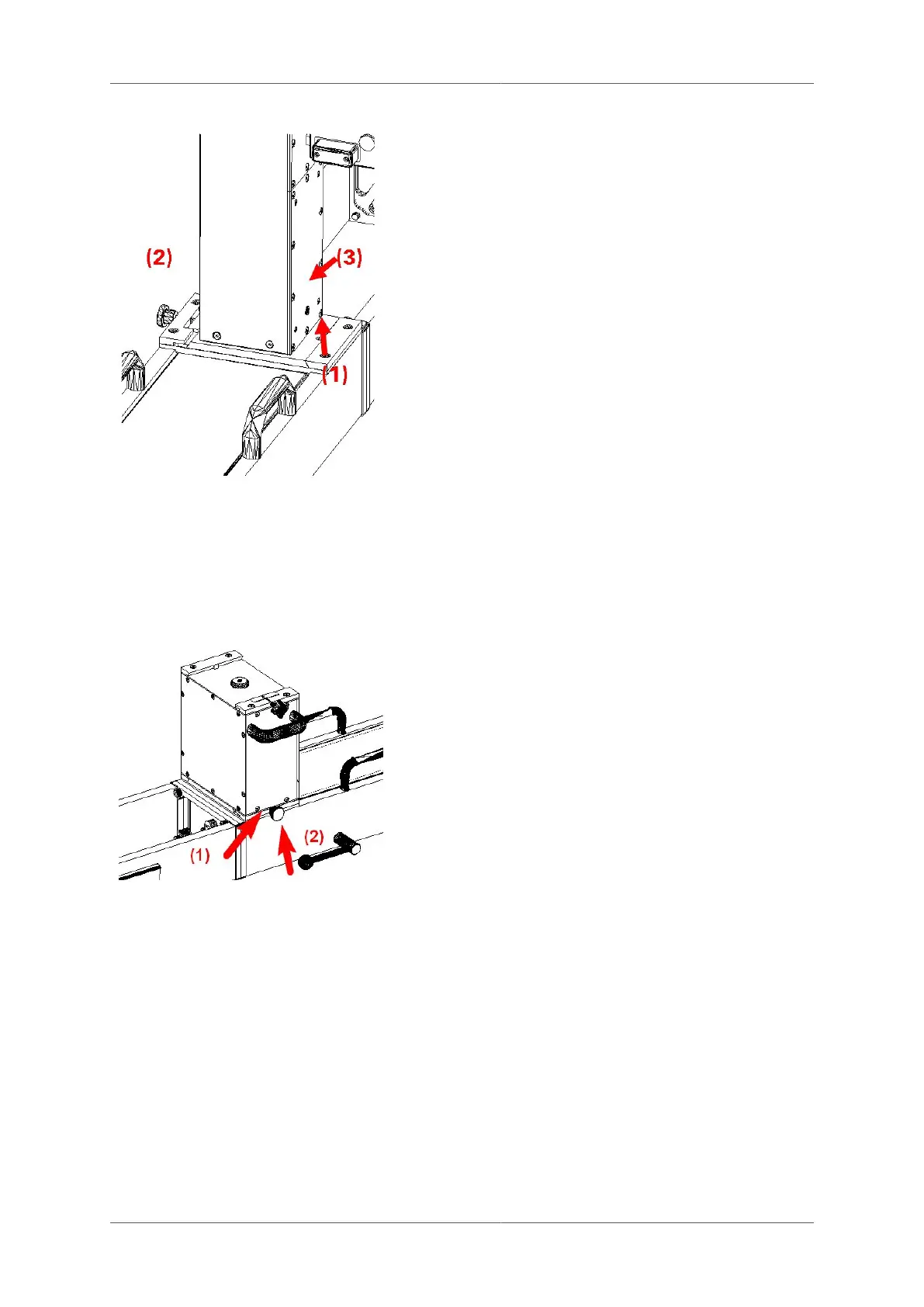
Line up indentation marked (1) on the base
plate of the Profiler FX column with the
protrusion and slide it into position.
■
Fully tighten the screw marked (2) and
ensure that the base plate is pushed right
against the back.
■
Connect the cable between the Profiler
FX at (3) and the track trolley TGS FX
serial port A. The same cable serves for
the data communication and for the power
supply. See also Section 4.2, “Cables and
connections for TGS FX” on page 44.
4.5 Installation of the Height Adaptor GHA 200
Configuration VMS 1000 and VMS 3000: The Height Adaptor GHA 200 is installed on the track
trolley GRP TSC as follows:
■
Ensure that the track trolley is securely
fastened together.
■
Line up indentation marked (1) on the base
plate of the GHA 200 height adaptor with
the protrusion and slide into position.
■
Fully tighten the screw marked (2) and
ensure that the base plate is pushed right
against the back.
■
Install the automatic tribrach GDA 12 onto
the GHA 200 with the same principle.
■
Install the total station onto the automatic
tribrach GDA 12.
■
Connect all cables from between the
GHA 200 height adaptor and the attached
devices (track trolley GRP TSC, automatic
tribrach GAD 12 and total station). See
also Section 4.2, “Cables and connections
for TGS FX” on page 44.
4.6 Installation of additional components for use in
absolute mode (Leica TPS System)
4.6.1 On the track trolley TGS FX
Page 46 of 114 © Amberg Technologies AG, 2023